The concept of network technologies, their role in management processes at enterprises. Types of network technologies of local networks What is the purpose of network technologies
Modern network technologies
Plan
What is a local area network?
Computer network hardware. Local area network topologies
Physical topologies of local area networks
Logical topologies of local area networks
Connectors and connectors
Coaxial cable
Twisted pair
Information transmission over fiber optic cables
Communication equipment
Equipment and technologies of wireless networks
Technologies and protocols of local area networks
Addressing computers on the network and basic network protocols
Network facilities of MS Windows operating systems
Network Resource Management Concepts
Possibilities of OS of the MS Windows family for organizing work in a local network
Configuring Network Component Settings
Configuring connection parameters
Connecting a network printer
Mapping a network drive
What is a local area network?
The problem of transferring information from one computer to another has existed since the advent of computers. Various approaches were used to solve it. The most common, in the recent past, "courier" approach was to copy information to removable media (CDM, CD, etc.), transfer to the destination and copy it again, but from the removable media to the recipient's computer. Currently, such methods of moving information are giving way to network technologies. Those. computers are somehow connected to each other, and the user has the ability to transfer information to its destination without leaving the table.
A set of computer devices that have the ability to communicate with each other for information is commonly called a computer network. In most cases, two types of computer networks are distinguished: local (LAN - LocalAreaNetwork) and global (WAN - Wide-AreaNetwork). In some variants of the classification, a number of additional types are considered: urban, regional, etc., however, all these types (in essence) in most cases are variants of global networks of various sizes. The most common variant of classification of networks into local and global by geography. Those. a local area network in this case is understood as a set of a finite number of computers located in a limited area (within the same building or neighboring buildings), connected by information channels with high speed and reliability of data transmission and designed to solve a set of interrelated problems.
Computer network hardware. Local area network topologies
All computers of subscribers (users) operating within the local computer network must be able to interact with each other, i.e. to be related. The way of organizing such links significantly affects the characteristics of a local computer network and is called its topology (architecture, configuration). Distinguish between physical and logical topology. The physical topology of a local area network is understood as the physical location of the computers that make up the network and the way they are connected to each other by conductors. The logical topology determines the way information flows and very often does not coincide with the chosen physical topology of the local area network subscribers' connection.
Physical topologies of local area networks
There are four main physical topologies used in the construction of local area networks.
The bus topology (Fig. 1) assumes that all computers are connected to one common conductor. Special matching devices called terminators are placed at both ends of such a conductor. The main advantages of this topology are low cost and ease of installation. The disadvantages include the problematic localization of the fault location and low reliability: damage to the cable anywhere leads to the termination of the exchange of information between all computers in the network. Due to the peculiarities of the propagation of an electrical signal, even if two computers trying to exchange information are physically connected to each other, in the absence of a terminator at one end of such a "piece" of the bus, communication between them will be impossible.
In a ring topology (Fig. 2), each network subscriber is associated with two nearby subscribers. The advantages and disadvantages are similar to those discussed for the bus topology.
Star topology involves laying a separate cable for each computer in the network that connects all network subscribers to a certain center. The center of the star can be a computer or a special connecting device called a hub (Fig. 3). The advantage of this topology is higher reliability. A break in any conductor "disconnects" only one subscriber. The bottleneck in this topology is the hub. If it breaks down, the operation of the entire network is blocked. The disadvantage is the higher cost of the equipment (considering the increase in the total length of the conductors, in comparison with the previous topologies, as well as the cost of additional equipment - the hub).
From the point of view of reliability and speed of information exchange, the fully connected topology has the best characteristics (Fig. 4). In this case, network subscribers are provided with a separate communication channel with each of the other subscribers. However, in terms of cost, this topology loses to all other options.
The listed topologies are basic. Most local area networks created in various organizations have a more complex structure and are various combinations of the above-mentioned topologies.
Logical topologies of local area networks
Logical topology determines the nature of the distribution of information over a computer network. When transferring information from one subscriber of the network to another subscriber, this information is properly "formalized". The transmitted data is formed into standard fragments (packets, datagrams). In addition to the actual transmitted data (numbers, texts, pictures, etc.), an address (a receiver of information or both receivers and a transmitter), control information (so that you can check whether the packet has been received in full or only part of it) and a number of others are added to the packet. information. Let's consider three main variants of logical topologies of local area networks.
The logical bus defines equal access to the network for all subscribers. In this case, the transmitter puts a packet of information into the network, and all other subscribers "having heard" the transmitted information analyze it. If the subscriber finds his address in the package, he “keeps” this information for himself, if the address turns out to be someone else's, he ignores it. If, at the time of information transmission by one subscriber, another subscriber "wedges into the conversation", there is an overlap of packets, called a collision. Collisions lead to "mixing" of packages and the inability to figure out "who said what." Having detected a collision, the transmitting subscriber "falls silent" for a time interval of a random duration, and then repeats the attempt to transmit information. With a very large number of subscribers in the network, the probability of collisions increases dramatically, and the network becomes inoperable.
The logical ring assumes that information travels a full "circle" and comes to the source, i.e. to the point from which it was sent. In this case, each subscriber compares the address of the "recipient" with his own. If the addresses match, the information is copied to the buffer, the packet is marked as “reaching the destination” and is transmitted to the next subscriber. If the addresses do not match, the packet is sent unmarked. When a subscriber received a packet sent "with his own hand" and marked "accepted", he does not transmit it further and another subscriber of the network can enter into work.
The logical topology of a star (and its version is a tree) is focused on establishing a communication channel between a receiver and a transmitter by means of switches. Those. in the absence of a switch, it is impossible to communicate with each other even for two network subscribers. When transferring data from one subscriber to another, everyone else is waiting for the end of the transfer.
Connectors and connectors
Currently, several types of conductors are used in local area networks. By the physical nature of the transmitted signal, electrical conductors and optical conductors are distinguished. In addition, equipment can be used for organizing local area networks by means of wireless channels.
Coaxial cable
Coaxial cable (Fig. 5) is a conductor enclosed in a braided shield. The conductor is protected from contact with the braiding by a tubular insulator. An important characteristic of cable systems in general and coaxial cable in particular is characteristic impedance or impedance. In local area networks, a coaxial cable with a characteristic impedance of 50 ohms is used and (much less often) in ARCnet networks, a cable with an impedance of 93 ohms is used. There are two types of coaxial cable - thick (outer diameter about 10 mm) and thin (outer diameter about 5 mm). With the same value of the characteristic impedance, thick and thin coaxial cables have different characteristics along the length of the cable segment and the number of supported network subscribers. A thick coaxial cable has a maximum segment length of 500 meters and a maximum number of connection points 100. A thin coaxial cable has a maximum segment length of 185 meters and a maximum number of connection points of 30.
Local area network networking technologies
In local networks, as a rule, a shared data transmission medium (mono-channel) is used and the main role is assigned to the protocols of the physical and channel levels, since these levels to the greatest extent reflect the specifics of local networks.
Network technology is an agreed set of standard protocols and software and hardware that implements them, sufficient for building a computer network. Network technologies are called core technologies or network architectures.
The network architecture defines the topology and method of access to the data transmission medium, cable system or data transmission medium, the format of network frames, the type of signal coding, and the transmission rate. In modern computer networks, technologies or network architectures such as Ethernet, Token-Ring, ArcNet, FDDI are widely used.
Network Technology IEEE802.3 / Ethernet
This architecture is currently the most popular in the world. Popularity is ensured by simple, reliable and inexpensive technologies. Classic Ethernet uses a standard coaxial cable of two types (thick and thin).
However, the version of Ethernet using twisted pairs as a transmission medium has become more and more widespread, since their installation and maintenance are much easier. Ethernet networks use bus and passive star topologies, and the access method is CSMA / CD.
The IEEE802.3 standard, depending on the type of data transmission medium, has modifications:
• 10BASE5 (thick coaxial cable) - provides a data transfer rate of 10 Mbit / s and a segment length of up to 500m;
• 10BASE2 (thin coaxial cable) - provides a data transfer rate of 10 Mbit / s and a segment length of up to 200m ;;
• 10BASE-T (unshielded twisted pair) - allows you to create a network in a star topology. The distance from the hub to the end node is up to 100m. The total number of nodes must not exceed 1024;
• 10BASE-F (fiber optic) - allows you to create a network in a star topology. Distance from the hub to the end node is up to 2000m.
In the development of Ethernet technology, high-speed options have been created: IEEE802.3u / Fast Ethernet and IEEE802.3z / Gigabit Ethernet. The basic topology used in Fast Ethernet and Gigabit Ethernet networks is passive star.
The Fast Ethernet network technology provides a transmission speed of 100 Mbit / s and has three modifications:
• 100BASE-T4 - unshielded twisted pair (quad twisted pair) is used. Distance from the hub to the end node up to 100m;
• 100BASE-TX - two twisted pairs are used (unshielded and shielded). Distance from the hub to the end node up to 100m;
• 100BASE-FX - Fiber optic cable is used (two fibers in the cable). Distance from the hub to the end node up to 2000m; ...
Gigabit Ethernet - Provides 1000 Mbps transfer rates. The following modifications of the standard exist:
1000BASE-SX - a fiber-optic cable with a light wavelength of 850 nm is used.
• 1000BASE-LX - a fiber optic cable with a light wavelength of 1300 nm is used.
• 1000BASE-CX - shielded twisted pair is used.
• 1000BASE-T - Uses a quadruple unshielded twisted pair.
Fast Ethernet and Gigabit Ethernet networks are compatible with Ethernet networks, so it is easy and simple to connect Ethernet, Fast Ethernet and Gigabit Ethernet segments into a single computer network.
The only drawback of this network is the lack of a guarantee of the time of access to the environment (and mechanisms for providing priority service), which makes the network unpromising for solving real-time technological problems. Certain problems are sometimes created by the limitation on the maximum data field, equal to ~ 1500 bytes.
Different coding schemes are used for different Ethernet speeds, but the access algorithm and frame format remains unchanged, which guarantees software compatibility.
An Ethernet frame has the format shown in Figure ..
Ethernet frame format (the numbers at the top of the figure show the size of the field in bytes)
Field preamble contains 7 bytes 0xAA and is used to stabilize and synchronize the environment (alternating signals CD1 and CD0 with the final CD0), followed by the field SFD(start frame delimiter = 0xab), which is designed to detect the start of the frame. Field EFD(end frame delimiter) specifies the end of the frame. Checksum field ( CRC - cyclic redundancy check), as well as the preamble, SFD and EFD, are generated and controlled at the hardware level. In some protocol modifications, the efd field is not used. The user can access fields starting with recipient addresses and ending with the field information, inclusive. The crc is followed by an interpacket gap (IPG) of 9.6 microseconds or more. The maximum frame size is 1518 bytes (preamble, SFD and EFD fields are not included here). The interface scans all packets following the cable segment to which it is connected, because to determine whether the received packet is correct and to whom it is addressed, you can only accept it in full. The correctness of the packet by CRC, by length and multiplicity of an integer number of bytes is performed after checking the destination address.
When a computer is connected to the network directly using a switch, the limitation on the minimum frame length is theoretically removed. But work with shorter frames in this case will become possible only when replacing the network interface with a non-standard one (moreover, for both the sender and the receiver)!
If in the frame field protocol / type If a code less than 1500 is written, then this field characterizes the length of the frame. Otherwise, it is the protocol code, the packet of which is encapsulated in the Ethernet frame.
Access to the Ethernet channel is based on the algorithm CSMA / CD (carrier sense multiple access with collision detection).In Ethernet, any station connected to the network can try to start transmitting a packet (frame) if the cable segment to which it is connected is free. Whether the segment is free, the interface determines by the absence of a "carrier" for 9.6 µs. Since the first bit of the packet does not reach the rest of the network stations simultaneously, it may happen that two or more stations will attempt to transmit, especially since the delays in repeaters and cables can reach quite large values. These matching attempts are called collisions. A collision (collision) is recognized by the presence of a signal in the channel, the level of which corresponds to the operation of two or more transceivers at the same time. When a collision is detected, the station interrupts the transmission. The attempt can be resumed after an exposure time (multiple of 51.2 μs, but not exceeding 52 ms), the value of which is a pseudo-random value and is calculated by each station independently (t = RAND (0.2 min (n, 10)), where n is the contents of the retry counter, and the number 10 is the backofflimit).
Usually, after a collision, time is split into a number of discrete domains with a length equal to twice the packet propagation time in a segment (RTT). For the maximum possible RTT, this time is 512 bit cycles. After the first collision, each station waits for 0 or 2 time domains before making another attempt. After the second collision, each of the stations can wait 0, 1, 2 or 3 time domains, etc. After the n-th collision, the random number lies in the range 0 - (2 n - 1). After 10 collisions, the maximum random exposure stops growing and remains at 1023.
Thus, the longer the cable segment, the longer the average access time.
After the delay, the station increases the attempts counter by one and starts the next transmission. The default limit for the number of attempts is 16, if the number of attempts is exhausted, the connection is terminated and a corresponding message is issued. The transmitted long frame helps to "synchronize" the start of transmission of packets by several stations. Indeed, during the transmission time, with a noticeable probability, there may be a need for transmission from two or more stations. The moment they detect the completion of the packet, the IPG timers will be enabled. Fortunately, the information about the completion of the packet transmission does not reach the stations of the segment simultaneously. But the delays with which this is connected are also the reason that the fact that a new packet has begun to be transmitted by one of the stations is not immediately known. If several stations are involved in a collision, they can notify other stations about this by sending a "jam" signal (jam - at least 32 bits). The content of these 32 bits is not regulated. This arrangement makes re-collision less likely. The source of a large number of collisions (in addition to information overload) can be the exorbitant total length of a logical cable segment, too many repeaters, a broken cable, the absence of a terminator (50-ohm cable matcher), or a malfunction of one of the interfaces. But collisions in themselves are not something negative - they are a mechanism that regulates access to the network environment.
In Ethernet, with synchronization, the following algorithms are possible:
A.
- If the channel is free, the terminal transmits a packet with probability 1.
- If the channel is busy, the terminal waits for it to be released, after which the transmission is performed.
B.
- If the channel is free, the terminal transmits a packet.
- If the channel is busy, the terminal determines the time of the next transmission attempt. The time of this delay can be given by some statistical distribution.
V.
- If the channel is free, the terminal transmits a packet with probability p, and with probability 1-p it postpones transmission for t seconds (for example, to the next time domain).
- If the attempt is repeated with a free channel, the algorithm does not change.
- If the channel is busy, the terminal waits until the channel is free, and then acts again according to the algorithm of point 1.
Algorithm A seems attractive at first glance, but it contains the possibility of collisions with a probability of 100%. Algorithms B and C are more robust against this problem.
The effectiveness of the CSMA algorithm depends on how quickly the transmitting side learns about the fact of the collision and interrupts the transmission, because the continuation is pointless - the data has already been damaged. This time depends on the length of the network segment and the delays in the equipment of the segment. Twice the delay value determines the minimum packet length for such a network. If the packet is shorter, it can be transmitted without the transmitting side knowing that it was damaged by the collision. For modern Ethernet LANs, built on switches and full duplex connections, this problem is irrelevant.
In order to clarify this statement, consider the case when one of the stations (1) transmits a packet to the most distant computer (2) in a given network segment. Let the signal propagation time to this machine be equal to T. Suppose also that machine (2) will try to start transmitting just at the moment the packet arrives from station (1). In this case, the station (1) learns about the collision only 2T after the start of transmission (the propagation time of the signal from (1) to (2) plus the propagation time of the collision signal from (2) to (1)). It should be borne in mind that collision detection is an analog process and the transmitting station must "listen" to the signal in the cable during transmission, comparing the reading result with what it is transmitting. It is important that the signal coding scheme is capable of collision detection. For example, the sum of two signals with level 0 will not allow you to do this. You might think that transmission of a short packet with distortion due to collision is not such a big problem, delivery control and retransmission can solve the problem.
It should only be taken into account that retransmission in the case of a collision registered by the interface is carried out by the interface itself, and retransmission in the case of response delivery control is performed by the application process, requiring the resources of the workstation CPU.
Double turn time and collision detection
Clear recognition of collisions by all stations on the network is a prerequisite for the correct operation of the Ethernet network. If any transmitting station does not recognize the collision and decides that the data frame was transmitted by it correctly, then this data frame will be lost. Due to the overlap of signals during a collision, the information of the frame will be distorted, and it will be rejected by the receiving station (possibly due to a mismatch of the checksum). Most likely, the garbled information will be retransmitted by some higher-level protocol, such as a transport or connection-oriented application protocol. But the retransmission of the message by the upper layer protocols will occur at a much longer time interval (sometimes even after a few seconds) compared to the microsecond intervals that the Ethernet protocol operates. Therefore, if collisions are not reliably recognized by the nodes of the Ethernet network, then this will lead to a noticeable decrease in the useful bandwidth of this network.
For reliable collision detection, the following relationship must be met:
T min> = PDV,
where T min is the transmission time of the minimum frame length, and PDV is the time it takes for the collision signal to propagate to the farthest network node. Since, in the worst case, the signal must pass twice between the stations of the network most distant from each other (an undistorted signal passes in one direction, and the signal already distorted by the collision propagates on the way back), this time is called double turnover time (Path Delay Value, PDV).
If this condition is met, the transmitting station must have time to detect the collision caused by its transmitted frame, even before it finishes transmitting this frame.
Obviously, the fulfillment of this condition depends, on the one hand, on the length of the minimum frame and the network bandwidth, and on the other hand, on the length of the network cable system and the speed of signal propagation in the cable (for different types of cable, this speed is slightly different).
All parameters of the Ethernet protocol are selected in such a way that during normal operation of network nodes, collisions are always clearly recognized. When choosing the parameters, of course, the above relationship was also taken into account, linking the minimum frame length and the maximum distance between stations in the network segment.
In the Ethernet standard, it is accepted that the minimum length of the frame data field is 46 bytes (which, together with the service fields, gives the minimum frame length of 64 bytes, and together with the preamble - 72 bytes or 576 bits). From here, a limitation on the distance between stations can be determined.
So, in 10 Mbit Ethernet, the transmission time of a minimum frame length is 575 bit slots, therefore, the double turnover time should be less than 57.5 μs. The distance that the signal can travel during this time depends on the type of cable and for a thick coaxial cable is approximately 13,280 m. Considering that during this time the signal must pass through the communication line twice, the distance between two nodes should not be more than 6,635 m In the standard, the value of this distance is chosen significantly less, taking into account other, more stringent restrictions.
One of these limitations is related to the maximum allowable signal attenuation. To ensure the necessary signal power during its passage between the stations of a cable segment most distant from each other, the maximum length of a continuous segment of a thick coaxial cable, taking into account the attenuation introduced by it, was chosen at 500 m.Obviously, on a cable of 500 m, the conditions for collision detection will be fulfilled with a large margin for frames of any standard length, including 72 bytes (the time of a double turn over a 500 m cable is only 43.3 bit intervals). Therefore, the minimum frame length could be set even less. However, the technology developers did not begin to reduce the minimum frame length, meaning multi-segment networks, which are built from several segments connected by repeaters.
Repeaters increase the power of the signals transmitted from segment to segment, as a result, signal attenuation is reduced and a much longer network consisting of several segments can be used. In coaxial Ethernet implementations, the developers have limited the maximum number of segments in the network to five, which in turn limits the total network length to 2500 meters. Even in such a multi-segment network, the collision detection condition is still met with a large margin (compare the distance of 2500 m obtained from the condition of permissible attenuation with the distance of 6635 m calculated above for the maximum possible signal propagation time). However, in reality, the time margin is significantly less, since in multi-segment networks the repeaters themselves introduce an additional delay into the signal propagation of several tens of bit intervals. Naturally, a small margin was also made to compensate for deviations in the parameters of the cable and repeaters.
As a result of taking into account all these and some other factors, the ratio between the minimum frame length and the maximum possible distance between network stations was carefully selected, which ensures reliable collision detection. This distance is also called the maximum network diameter.
With an increase in the frame rate, which takes place in new standards based on the same CSMA / CD access method, for example Fast Ethernet, the maximum distance between network stations decreases in proportion to the increase in the transfer rate. In the Fast Ethernet standard, it is about 210 meters, and in the Gigabit Ethernet standard, it would be limited to 25 meters, if the developers of the standard did not take some measures to increase the minimum packet size.
PDV calculation
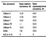
To simplify calculations, the IEEE reference data is usually used, which contains the values of the propagation delays of signals in repeaters, transceivers and various physical environments. Table 3.5 shows the data required to calculate the PDV value for all physical Ethernet standards. The bit interval is denoted as bt.
Table 3.5.Data for calculating the PDV value

The 802.3 committee tried to simplify the calculations as much as possible, so the data shown in the table includes several stages of the signal at once. For example, repeater delays consist of input transceiver delay, repetition block delay, and output transceiver delay. Nevertheless, in the table, all these delays are represented by a single value called the segment base. In order not to have to add the delays introduced by the cable twice, the table gives twice the delays for each type of cable.
The table also uses concepts such as left segment, right segment, and intermediate segment. Let us explain these terms using the example of the network shown in Fig. 3.13. The left segment is the segment in which the signal path begins from the output of the transmitter (output T x in Fig. 3.10) of the end node. For example, this is a segment 1 ... Then the signal goes through intermediate segments 2-5 and reaches the receiver (input R x in Fig. 3.10) of the most distant node of the most distant segment 6, which is called the right one. This is where, in the worst case, a collision of frames occurs and a collision occurs, which is what the table implies.

Rice. 3.13.An example of an Ethernet network composed of segments of different physical standards
Associated with each segment is a constant delay called baseline, which depends only on the type of segment and on the position of the segment along the signal path (left, intermediate, or right). The base of the right segment in which the collision occurs is much larger than the base of the left and intermediate segments.
In addition, a signal propagation delay along the segment cable is associated with each segment, which depends on the segment length and is calculated by multiplying the signal propagation time along one meter of the cable (in bit intervals) by the cable length in meters.
The calculation consists in calculating the delays introduced by each cable segment (the signal delay for 1 m of cable shown in the table is multiplied by the segment length), and then summing these delays with the bases of the left, intermediate and right segments. The total PDV should not exceed 575.
Since the left and right segments have different values of the basic delay, then in the case of different types of segments at the remote edges of the network, it is necessary to perform calculations twice: once to accept a segment of one type as the left segment, and the second - a segment of a different type. The result is the maximum PDV value. In our example, the extreme network segments belong to the same type - the 10Base-T standard, so double calculation is not required, but if they were segments of different types, then in the first case it would be necessary to accept as the left segment between the station and the hub 1 , and in the second, consider the left segment between the station and the hub 5 .
The network shown in the figure in accordance with the rule of 4 hubs is not correct - in the network between segment nodes 1 and 6 there are 5 hubs, although not all segments are lOBase-FB segments. In addition, the total length of the network is 2800 m, which violates the 2500 m rule. Let's calculate the PDV value for our example.
Left segment 1 / 15.3 (base) + 100 * 0.113 = 26.6.
Intermediate segment 2/ 33,5 + 1000 * 0,1 = 133,5.
Intermediate segment 3/ 24 + 500 * 0,1 = 74,0.
Intermediate segment 4/ 24 + 500 * 0,1 = 74,0.
Intermediate segment 5/ 24 + 600 * 0,1 = 84,0.
Right segment 6 /165 + 100 * 0,113 = 176,3.
The sum of all the components gives a PDV value of 568.4.
Since the PDV value is less than the maximum allowable value of 575, this network passes according to the criterion of the double signal turnover time, despite the fact that its total length is more than 2500 m, and the number of repeaters is more than 4
PW calculation
To recognize the network configuration as correct, it is also necessary to calculate the decrease in the interframe spacing by the repeaters, that is, the PW value.
To calculate the PW, you can also use the values of the maximum values of the decrease in the interframe interval when passing repeaters of various physical media, recommended by the IEEE and given in table. 3.6.
Table 3.6.Reduction of interframe spacing by repeaters

Based on this data, we calculate the PVV value for our example.
Left segment 1 10Base-T: 10.5 bt reduction.
Intermediate segment 2 10Base-FL: 8.
Intermediate segment 3 10Base-FB: 2.
Intermediate segment 4 10Base-FB: 2.
Intermediate segment 5 10Base-FB: 2.
The sum of these values gives a PW of 24.5, which is less than the 49 bit-slot limit.
As a result, the network shown in the example complies with the Ethernet standards in all parameters related to both segment lengths and the number of repeaters.
Maximum Ethernet performance
The number of Ethernet frames processed per second is often cited by bridge / switch and router manufacturers as a key performance characteristic of these devices. In turn, it is interesting to know the net maximum throughput of an Ethernet segment in frames per second in the ideal case, when there are no collisions on the network and there are no additional delays introduced by bridges and routers. This indicator helps to assess the performance requirements of communication devices, since each port of a device cannot receive more frames per unit of time than the corresponding protocol allows.
For communication equipment, the most difficult mode is the processing of frames of the shortest length. This is due to the fact that a bridge, switch or router spends approximately the same time to process each frame, associated with viewing the packet forwarding table, generating a new frame (for a router), etc. per unit of time, naturally, more than frames of any other length. Another performance characteristic of communication equipment - bits per second - is used less often, since it does not say what frame size the device was processing at the same time, and it is much easier to achieve high performance, measured in bits per second, on frames of the maximum size.
Using the parameters given in table. 3.1, we will calculate the maximum performance of the Ethernet segment in such units as the number of transmitted frames (packets) of the minimum length per second.
NOTEWhen referring to the bandwidth of networks, the terms frame and packet are usually used interchangeably. Accordingly, frames-per-second, fps and packets-per-second, pps units are similar.
To calculate the maximum number of frames of the minimum length passing over the Ethernet segment, note that the size of the minimum frame length together with the preamble is 72 bytes or 576 bits (Fig. 3.5.), So 57.5 μs is spent on its transmission. Adding an interframe spacing of 9.6 μs, we find that the repetition period of the minimum frame length is 67.1 μs. Hence, the maximum possible throughput of an Ethernet segment is 14,880 fps.
Rice. 3.5.To the calculation of the throughput of the Ethernet protocol
Naturally, the presence of several nodes in the segment reduces this value due to waiting for access to the medium, as well as due to collisions that lead to the need for retransmission of frames.
Maximum length frames of Ethernet technology have a field length of 1500 bytes, which together with the service information gives 1518 bytes, and with the preamble is 1526 bytes or 12208 bits. The maximum possible throughput of an Ethernet segment for maximum frame lengths is 813 fps. Obviously, when working with large frames, the load on bridges, switches and routers is quite noticeably reduced.
Now let's calculate the maximum usable bandwidth in bits per second that Ethernet segments have when using frames of different sizes.
Under useful protocol bandwidth refers to the bit rate of user data that is carried by the data field of the frame. This throughput is always less than the nominal Ethernet bit rate due to several factors:
· service information of the frame;
· Interframe Gaps (IPG);
· waiting for access to the environment.
For frames with a minimum length, the usable bandwidth is:
C P = 14880 * 46 * 8 = 5.48 Mbps.
This is much less than 10 Mbit / s, but it should be taken into account that frames of the minimum length are used mainly for transmitting receipts, so this speed has nothing to do with the transfer of the actual file data.
For frames of maximum length, the usable bandwidth is:
C P = 813 * 1500 * 8 = 9.76 Mbps,
which is very close to the nominal speed of the protocol.
We emphasize once again that such a speed can be achieved only when two interacting nodes in the Ethernet network are not interfered with by other nodes, which is extremely rare.
Using medium-sized frames with a 512-byte data field, the network bandwidth will be 9.29 Mbps, which is also close enough to the maximum bandwidth of 10 Mbps.
ATTENTIONThe ratio of the current network bandwidth to its maximum bandwidth is called network utilization. In this case, when determining the current throughput, the transmission of any information over the network, both user and service information, is taken into account. The coefficient is an important indicator for technologies of shared media, since with a random nature of the access method, a high value of the utilization coefficient often indicates a low useful network bandwidth (that is, the transmission rate of user bottom) - nodes spend too much time on the procedure for gaining access and retransmitting frames after collisions.
In the absence of collisions and waiting for access, the network utilization depends on the size of the data field of the frame and has a maximum value of 0.976 when transmitting frames of the maximum length. Obviously, in a real Ethernet network, the average network utilization can differ significantly from this value. More complex cases of determining the network bandwidth, taking into account waiting for access and handling collisions, will be considered below.
Ethernet frame formats
The Ethernet technology standard described in the IEEE 802.3 document describes a single MAC layer frame format. Since the MAC layer frame must include the LLC layer frame described in the IEEE 802.2 document, according to the IEEE standards, only one version of the link layer frame can be used in the Ethernet network, the header of which is a combination of the MAC and LLC sublayer headers.
Nevertheless, in practice, in Ethernet networks at the link layer, frames of 4 different formats (types) are used. This is due to the long history of the development of Ethernet technology, which existed before the adoption of the IEEE 802 standards, when the LLC sublayer was not separated from the general protocol and, accordingly, the LLC header was not used.
A consortium of three firms Digital, Intel and Xerox in 1980 submitted to the 802.3 committee their proprietary version of the Ethernet standard (which, of course, described a certain frame format) as a draft international standard, but the 802.3 committee adopted a standard that differs in some details from DIX offers. The differences were also in the frame format, which gave rise to the existence of two different types of frames in Ethernet networks.
Another frame format is a result of Novell's efforts to speed up its protocol stack over Ethernet.
Finally, the fourth frame format is the result of the 802.2 committee's efforts to bring previous frame formats to some common standard.
Differences in frame formats can lead to incompatibility between hardware and network software that is designed to work with only one Ethernet frame standard. However, today almost all network adapters, network adapter drivers, bridges / switches and routers can work with all Ethernet technology frame formats used in practice, and the frame type is recognized automatically.
Below is a description of all four types of Ethernet frames (here, a frame means the entire set of fields that relate to the link layer, that is, the fields of the MAC and LLC layers). One and the same frame type can have different names, so below for each frame type are given several of the most common names:
· 802.3 / LLC frame (802.3 / 802.2 frame or Novell 802.2 frame);
· Raw 802.3 frame (or Novell 802.3 frame);
· Ethernet DIX frame (or Ethernet II frame);
· Ethernet SNAP frame.
The formats for all of these four types of Ethernet frames are shown in Fig. 3.6.

conclusions
· Ethernet is the most widely used local area network technology today. Broadly speaking, Ethernet is a family of technologies that includes a variety of proprietary and standard options, most notably the proprietary DIX Ethernet option, the 10Mbit options of the IEEE 802.3 standard, and the new high-speed Fast Ethernet and Gigabit Ethernet technologies. Nearly all types of Ethernet technologies use the same media separation method, the CSMA / CD random access method, which defines the overall technology.
· In a narrower sense, Ethernet is a 10-megabit technology described in the IEEE 802.3 standard.
· An important phenomenon in Ethernet networks is collision - a situation when two stations simultaneously try to transmit a data frame over a common medium. Collisions are an inherent property of Ethernet networks and are a consequence of the random access method adopted. The ability to clearly recognize collisions is due to the correct choice of network parameters, in particular, compliance with the ratio between the minimum frame length and the maximum possible network diameter.
· The network utilization factor, which reflects its congestion, is of great importance for the performance characteristics of the network. With values of this coefficient above 50%, the useful network bandwidth drops sharply: due to an increase in the intensity of collisions, as well as an increase in the waiting time for access to the environment.
· The maximum possible throughput of an Ethernet segment in frames per second is achieved with the transmission of frames of the minimum length and amounts to 14,880 fps. At the same time, the useful network bandwidth is only 5.48 Mbit / s, which is only slightly more than half of the nominal bandwidth - 10 Mbit / s.
· The maximum usable Ethernet bandwidth is 9.75 Mbps, which equates to a maximum frame length of 1518 bytes that are transmitted over the network at 513 fps.
· Without collisions and waiting for access utilization rate network depends on the size of the data field of the frame and has a maximum value of 0.96.
· Ethernet technology supports 4 different frame types that share a common host address format. There are formal signs by which network adapters automatically recognize the frame type.
· Depending on the type of physical medium, the IEEE 802.3 standard defines different specifications: 10Base-5, 10Base-2, 10Base-T, FOIRL, 10Base-FL, 10Base-FB. For each specification, the type of cable, the maximum lengths of continuous cable lengths, as well as the rules for using repeaters to increase the diameter of the network are determined: the 5-4-3 rule for coaxial networks, and the 4-hub rule for twisted pair and fiber.
· For a "mixed" network, consisting of different types of physical segments, it is useful to calculate the total length of the network and the allowed number of repeaters. The IEEE 802.3 committee provides a baseline for these calculations, which specifies the delays introduced by repeaters of various physical media specifications, network adapters and cable segments.
Network Technologies IEEE802.5 / Token-Ring
Token Ring networks, like Ethernet networks, are characterized by a shared data transmission medium, which in this case consists of lengths of cable connecting all stations on the network in a ring. The ring is considered as a shared resource, and access to it requires not a random algorithm, as in Ethernet networks, but a deterministic one, based on the transfer of the right to use the ring to stations in a certain order. This right is transmitted using a special format frame called marker or token.
Token Ring networks operate at two bit rates - 4 and 16 Mbps. Mixing stations operating at different speeds in one ring is not allowed. Token Ring networks operating at 16 Mbps have some improvements in the access algorithm over the 4 Mbps standard.
Token Ring technology is more complex than Ethernet. It has the properties of fault tolerance. The Token Ring network defines network control procedures that use a ring-shaped feedback structure - a sent frame is always returned to the sending station. In some cases, detected network errors are eliminated automatically, for example, a lost token can be restored. In other cases, errors are only recorded, and their elimination is performed manually by the service personnel.
To control the network, one of the stations acts as a so-called active monitor... The active monitor is selected during ring initialization as the station with the maximum MAC address. If the active monitor fails, the ring initialization procedure is repeated and a new active monitor is selected. In order for the network to detect the failure of the active monitor, the latter, in a healthy state, generates a special frame of its presence every 3 seconds. If this frame does not appear on the network for more than 7 seconds, then the rest of the network stations begin the procedure for selecting a new active monitor.
Token Ring Frame Formats
There are three different frame formats in Token Ring:
· Marker;
· Data frame;
· break sequence
Physical layer of Token Ring technology
The IBM Token Ring standard originally envisaged building connections in a network using hubs called MAUs (Multistation Access Unit) or MSAU (Multi-Station Access Unit), that is, multiple access devices (Figure 3.15). Token Ring can have up to 260 nodes.

Rice. 3.15.Token Ring Physical Configuration
A Token Ring hub can be active or passive. A passive hub simply interconnects the ports with interconnects so that the stations connected to those ports form a ring. The passive MSAU does not perform signal amplification or resynchronization. Such a device can be considered a simple crossover unit with one exception - the MSAU ensures that a port is bypassed when a computer connected to that port is turned off. This function is necessary to ensure ring connectivity regardless of the state of the connected computers. Typically, the port is bypassed by relay circuits that are DC powered from the AC adapter, and when the AC adapter is turned off, the normally closed relay contacts connect the port input to its output.
An active hub performs signal regeneration functions and is therefore sometimes referred to as a repeater, as in the Ethernet standard.
The question arises - if the hub is a passive device, then how is the high-quality transmission of signals over long distances, which arise when several hundred computers are connected to the network? The answer is that in this case each network adapter takes on the role of a signal amplifier, and the network adapter of the active ring monitor plays the role of a resynchronization unit. Each Token Ring network adapter has a repeater block that can regenerate and resynchronize signals, but only the active monitor repeater block performs the latter function in the ring.
The resynchronization block consists of a 30-bit buffer, which receives Manchester signals with repetition intervals somewhat distorted during a revolution around the ring. With the maximum number of stations in the ring (260), the variation of the bit circulation delay around the ring can reach 3-bit intervals. The active monitor "inserts" its buffer into the ring and synchronizes the bit signals, outputting them at the required frequency.
In general, a Token Ring network has a combined star-ring configuration. End nodes are connected to MSAUs in a star topology, and the MSAUs themselves are combined through special Ring In (RI) and Ring Out (RO) ports to form a physical backbone ring.
All stations in the ring must operate at the same speed - either 4 Mbps or 16 Mbps. The cables connecting the station to the hub are called lobe cables, and the cables connecting the hubs are called trunk cables.
Token Ring technology allows the use of various types of cable to connect end stations and hubs: STP Type I, UTP Type 3, UTP Type 6, as well as fiber-optic cable.
When using shielded twisted pair STP Type 1 from the IBM cabling system range, up to 260 stations can be combined into a ring with a drop cable length of up to 100 meters, and when using an unshielded twisted pair pair, the maximum number of stations is reduced to 72 with a drop cable length of up to 45 meters.
The distance between passive MSAUs can be up to 100 m using STP Type 1 cable and 45 m using UTP Type 3 cable. Between active MSAUs, the maximum distance increases to 730 m or 365 m, respectively, depending on the type of cable.
The maximum ring length of Token Ring is 4000 m. The restrictions on the maximum ring length and the number of stations in a ring in Token Ring technology are not as stringent as in Ethernet technology. Here, these restrictions are largely related to the time of the marker revolution around the ring (but not only, there are other considerations that dictate the choice of restrictions). So, if the ring consists of 260 stations, then with a marker hold time of 10 ms, the marker will return to the active monitor in the worst case after 2.6 s, and this time is just the timeout of the marker rotation control. In principle, all of the timeout values in the network adapters of the Token Ring hosts are configurable, so you can build a Token Ring network with more stations and longer ring lengths.
conclusions
· Token Ring technology is developed primarily by IBM and also has IEEE 802.5 standard status, which reflects the most important advances in IBM technology.
· Token Ring networks use a token access method that ensures that each station gains access to the shared ring during the token revolution. Because of this property, this method is sometimes called deterministic.
· The access method is priority-based: 0 (lowest) to 7 (highest). The station itself determines the priority of the current frame and can seize the ring only when there are no higher priority frames in the ring.
· Token Ring networks operate at two speeds: 4 and 16 Mbps and can use shielded twisted pair, unshielded twisted pair, and fiber optic cable as the physical medium. The maximum number of stations in the ring is 260, and the maximum length of the ring is 4 km.
· Token Ring technology has elements of fault tolerance. Due to the feedback of the ring, one of the stations - the active monitor - continuously monitors the presence of the marker, as well as the turnover time of the marker and data frames. If the ring does not work correctly, the procedure for its reinitialization is started, and if it does not help, then the beaconing procedure is used to localize the faulty section of the cable or the faulty station.
· The maximum data field size of a Token Ring frame depends on the speed of the ring. For a speed of 4 Mbit / s it is about 5000 bytes, and at a speed of 16 Mbit / s it is about 16 KB. The minimum size of the frame data field is undefined, that is, it can be equal to 0.
· In a Token Ring network, stations are connected into a ring using hubs called MSAUs. The passive MSAU hub acts as a crossover panel that connects the output of the previous station in the ring with the input of the next. The maximum distance from the station to the MSAU is 100 m for STP and 45 m for UTP.
· The active monitor also acts as a repeater in the ring - it resynchronizes the signals passing through the ring.
· The ring can be built on the basis of an active MSAU concentrator, which in this case is called a repeater.
· A Token Ring network can be built on the basis of several rings, separated by bridges, routing frames on a "from source" basis, for which a special field with the route of the rings is added to the Token Ring frame.
Network Technology IEEE802.4 / ArcNet
An ArcNet network uses a bus and a passive star as its topology. Supports shielded and unshielded twisted pair and fiber optic cable. In the ArcNet network, a transfer of authority method is used to access the communication medium. ArcNet is one of the oldest and most popular networks. The main advantages of the ArcNet network include high reliability, low adapter cost, and flexibility. The main disadvantage of the network is the low data transfer rate (2.5 Mbit / s). The maximum number of subscribers is 255. The maximum network length is 6000 meters.
Network technology FDDI (Fiber Distributed Data Interface)
FDDI–a standardized specification for a high-speed fiber optic network architecture. The transmission speed is 100 Mbps. This technology is largely based on the Token-Ring architecture and uses deterministic token access to the data transmission medium. The maximum length of the network ring is 100 km. The maximum number of network subscribers is 500. The FDDI network is a very highly reliable network, which is created on the basis of two fiber-optic rings, which form the main and backup data transmission paths between nodes.
The main characteristics of the technology
FDDI technology is largely based on Token Ring technology, developing and improving its basic ideas. The developers of the FDDI technology set the following goals as the highest priority:
· increase the bit rate of data transmission up to 100 Mbps;
· to increase the fault tolerance of the network due to standard procedures for recovering it after failures of various kinds - cable damage, incorrect operation of a node, a hub, the occurrence of a high level of noise on the line, etc .;
· Make the most of the potential network bandwidth for both asynchronous and synchronous (delay-sensitive) traffic.
The FDDI network is built on the basis of two fiber-optic rings, which form the main and backup data transmission paths between the network nodes. Having two rings is the primary way to improve resiliency in an FDDI network, and nodes that want to take advantage of this increased reliability potential must be connected to both rings.
In normal network operation, data passes through all nodes and all cable sections of only the Primary ring, this mode is called Thru- "through" or "transit". Secondary ring is not used in this mode.
In the event of some type of failure, when part of the primary ring cannot transmit data (for example, a cable break or node failure), the primary ring is combined with the secondary (Figure 3.16), again forming a single ring. This network mode is called Wrap, that is, "folding" or "folding" the rings. The folding operation is performed by means of hubs and / or FDDI network adapters. To simplify this procedure, data on the primary ring is always transmitted in one direction (in the diagrams this direction is shown counterclockwise), and along the secondary - in the opposite direction (shown clockwise). Therefore, when a common ring of two rings is formed, the transmitters of the stations still remain connected to the receivers of neighboring stations, which makes it possible to correctly transmit and receive information by neighboring stations.

Rice. 3.16.Reconfiguring FDDI Rings on Failure
In the FDDI standards, a lot of attention is paid to various procedures that allow you to determine the presence of a network failure, and then make the necessary reconfiguration. The FDDI network can fully restore its operability in the event of single failures of its elements. With multiple failures, the network splits into several unconnected networks. FDDI technology complements Token Ring failure detection mechanisms with mechanisms for reconfiguring the data transmission path in the network, based on the availability of redundant links provided by the second ring.
Rings in FDDI networks are considered as a common shared data transmission medium, therefore a special access method is defined for it. This method is very close to the Token Ring access method and is also called the token ring method.
The difference in the access method is that the retention time of the token in the FDDI network is not constant, as in the Token Ring network. This time depends on the loading of the ring - with a small load it increases, and with large overloads it can decrease to zero. These changes in the access method apply only to asynchronous traffic, which is not critical to small frame transmission delays. For synchronous traffic, the token retention time is still a fixed value. A frame priority mechanism similar to that used in Token Ring technology is absent in FDDI technology. The technology developers decided that dividing traffic into 8 priority levels is redundant and it is enough to divide traffic into two classes - asynchronous and synchronous, the last of which is always served, even when the ring is overloaded.
Otherwise, frame forwarding between ring stations at the MAC level fully complies with Token Ring technology. FDDI stations use an early token deallocation algorithm similar to 16 Mbps Token Ring networks.
MAC layer addresses are in a standard IEEE 802 format. The FDDI frame format is close to the Token Ring frame format, the main differences are in the absence of priority fields. Address recognition, frame copying, and error features allow you to preserve the existing Token Ring procedures for processing frames by the sending station, intermediate stations and receiving stations.
In fig. 3.17 shows the correspondence of the structure of protocols to the FDDI technology with the seven-layer OSI model. FDDI defines a physical layer protocol and a link layer media access (MAC) sublayer protocol. Like many other LAN technologies, FDDI uses the LLC Data Link Control Sublayer protocol defined in the IEEE 802.2 standard. Thus, despite the fact that FDDI technology was developed and standardized by the ANSI institute, and not by the IEEE committee, it fully fits into the structure of the 802.

Rice. 3.17.FDDI technology protocol structure
A distinctive feature of the FDDI technology is the station control level - Station Management (SMT). It is the SMT layer that performs all the functions of managing and monitoring all other layers of the FDDI protocol stack. Each node of the FDDI network takes part in the management of the ring. Therefore, all nodes exchange special SMT frames for network management.
Resiliency of FDDI networks is provided by protocols and other layers: using the physical layer, network failures are eliminated for physical reasons, for example, due to a cable break, and using the MAC layer, logical network failures, for example, the loss of the required internal path for the transmission of tokens and data frames between the ports of the hub ...
conclusions
· FDDI technology was the first to use fiber-optic cable in local networks, as well as work at a speed of 100 Mbps.
· There is significant continuity between Token Ring and FDDI technologies: both are characterized by a ring topology and a token access method.
· FDDI technology is the most resilient local area network technology. In case of single failures of the cable system or station, the network, due to the "folding" of the double ring into a single one, remains fully operational.
· The FDDI token access method works differently for synchronous and asynchronous frames (the type of frame is determined by the station). To transmit a synchronous frame, the station can always capture the incoming token for a fixed time. To transmit an asynchronous frame, the station can capture the token only when the token has rotated around the ring fast enough, which indicates that there is no ring congestion. This access method, firstly, gives preference to synchronous frames, and secondly, it regulates the ring load, slowing down the transmission of non-urgent asynchronous frames.
· FDDI uses fiber optic cables and Category 5 UTP (this version of the physical layer is called TP-PMD) as the physical medium.
· The maximum number of double connection stations in a ring is 500, the maximum diameter of a double ring is 100 km. The maximum distances between neighboring nodes for multimode cable are 2 km, for twisted pair UPT category 5-100 m, and for single-mode fiber depend on its quality
Network technology is a consistent set of standard protocols and software and hardware that implements them, sufficient for building computer networks.
Protocol Is a set of rules and conventions that determine how devices on a network exchange data.
Currently, the following network technologies dominate: Ethernet, Token Ring, FDDI, ATM.
Ethernet technology
Ethernet technology was created by XEROX in 1973. The basic principle behind Ethernet is a random method of accessing a shared data transmission medium (multiple access method).
The logical topology of an Ethernet network is always bus-based, so data is transmitted to all nodes in the network. Each node sees each transmission and distinguishes the data intended for it by the address of its network adapter. At a time, only one node can make a successful transfer, so there must be some agreement between the nodes on how to use the same cable together so as not to interfere with each other. This agreement defines the Ethernet standard.
As the network load grows, it becomes more and more necessary to transfer data at the same time. When this happens, the two transmissions collide, filling the bus with information garbage. This behavior is known under the term "collision", that is, the occurrence of a conflict.
Each transmission system, upon detecting a collision, immediately stops sending data, and action is taken to remedy the situation.
Although most collisions that occur on a typical Ethernet network are resolved within microseconds and their occurrence is natural and expected, the main disadvantage is that the more traffic on the network, the more collisions, the more dramatically the network performance drops and a collapse can occur. that is, the network is clogged with traffic.
Traffic- the flow of messages in the data transmission network.
Token Ring technology
Token Ring technology was developed by IBM in 1984. Token Ring technology uses a completely different access method. The logical token ring network has a ring topology. A special message known as a Token is a special three-byte packet that is constantly circulating around a logical ring in one direction. When the token passes through a node ready to transmit data to the network, it grabs the token, attaches the data to be sent to it, and then transmits the message back to the ring. The message continues its "journey" around the ring until it reaches its destination. Until the message is received, no node will be able to forward data. This access method is known as token passing. It eliminates collisions and arbitrary latencies like Ethernet.
FDDI technology
Fiber Distributed Data Interface (FDDI) technology is the first local area network technology in which the data transmission medium is a fiber optic cable. FDDI technology is largely based on Token Ring technology, developing and improving its basic ideas. The FDDI network is built on the basis of two fiber-optic rings, which form the main and backup data transmission paths between the network nodes. Having two rings is the main way to improve resiliency in an FDDI network, and nodes that want to take advantage of this increased reliability potential must be connected to both rings.
In normal network operation, data passes through all nodes and all cable sections of the primary ring only, the secondary ring is not used in this mode. In the event of some type of failure, where part of the primary ring cannot transmit data (for example, a cable break or node failure), the primary ring is combined with the secondary, again forming a single ring.
Rings in FDDI networks are considered as a general data transmission medium, therefore a special access method is defined for it, which is very close to the access method of Token Ring networks. The difference is that the token retention time in the FDDI network is not constant, as in Token Ring. It depends on the load on the ring - with a small load it increases, and with large overloads it can decrease to zero for asynchronous traffic. For synchronous traffic, the token hold time remains a fixed value.
ATM technology
ATM (Asynchronous Transfer Mode) is the most advanced network technology. It is designed to transmit voice, data and video using a high-speed, connection-oriented, cell-switched protocol.
Unlike other technologies, ATM traffic is divided into 53 - byte cells (cells). Applying a predefined size data structure makes network traffic more easily quantifiable, predictable, and manageable. ATM is based on the transmission of information over a fiber optic cable using a star topology.
From the PIE Wiki
Modern networking technologies have contributed to a new technical revolution. In the United States, the creation of a single network of computers is given the same importance as the construction of expressways in the sixties. Therefore, the computer network is called the "information superhighway". To highlight the benefits that the network will bring to all users, Microsoft is talking about information "at their fingertips."
HIGH SPEED DATA CHANNELS
High-speed X.25 and ISDN channels can be used to transfer information. ISDN (Integrated Services Digital Network) allows representatives from different countries to organize videoconferences and discuss issues of interest without costly travel. To implement remote access, digital communication adapters and bridges are inserted into computers, and the slowest adapter for ISDN works many times faster than a modem. Special software has been developed to enable Windows 95 and its Internet browser to work with ISDN. It can be found and obtained free of charge from the World Wide Web Server at http://www.microsoft.com. At present, Russia is building a nationwide digital network with access to abroad, which will be able to provide ISDN communication services and provide remote access for end users to the local networks of their enterprises and interact with computer networks, including the Internet with a speed of 64 - 128 Kbit / with. Unfortunately, the implementation of ISDN faces a lot of difficulties, since expensive equipment is required and special lines must be laid.
LOCAL NETWORKS
A computer connected to a network is called a Workstation, a computer that provides its resources is a server, a computer that has access to shared resources is a client. Several computers located in the same room or functionally performing the same type of work: accounting or planning, registration of incoming products, etc., are connected to each other and combined into a working group so that they can share various resources: programs, documents , printers, fax, etc. The working group is organized so that the computers included in it contain all the resources necessary for normal operation. As a rule, a workgroup of more than 10-15 computers includes a dedicated server - a powerful enough computer that contains all the shared directories and special software to control access to the entire network or part of it. Server groups are combined into domains. A domain user can register on the network at any workstation in this domain and gain access to all its resources. Typically, on server networks, all shared printers are connected to print servers. From the point of view of organizing the interaction of computers, networks are divided into peer-to-peer (Peer-to-Peer Network) and with a dedicated server (Dedicated Server Network). In a peer-to-peer network, each computer plays an equal role. However, the increase in the number of computers on the network and the increase in the amount of data transferred leads to the fact that the network bandwidth becomes a bottleneck. Windows 95 is primarily designed to work in peer-to-peer networks to support the operation of a computer as a client of other networks. Windows 95, like Windows for Workgroups, can act as a server on a network. Compatibility with old MS-DOS and Windows Z.x network drivers is provided. The new operating system allows you to: share hard disks, printers, fax cards, organize peer-to-peer local area networks (LAN); use remote access and turn the office computer into a callable server; support 16-bit DOS network drivers. The network administrator can define the overall design of the desktop system, determine what operations are available to network users, and control the configuration of the desktop system. A network located in a relatively small area is called a local area network (LAN). In recent years, there has been an increase in the complexity of the LAN structure due to the creation of heterogeneous networks that unite different computer platforms. The ability to conduct video conferencing and use multimedia increases the software requirements of networks. Modern servers can store binary large objects (BLOBs) containing text, image, audio, and video files. In particular, if you need to get a database of the HR department over the network, then the BLOB technology will allow you to transfer not only personal data: last name, first name, patronymic, year of birth, but also portraits in digital form. Two server technologies There are two server technologies: file server technology and client / server architecture. The first model uses a file server that hosts most of the programs and data. At the request of the user, the necessary program and data are sent to him. Information processing is performed at the workstation. In systems with a client-server architecture, data exchange is carried out between the client application (front-end) and the server application (back-end). Data storage and processing is performed on a powerful server, which also controls access to resources and data. The workstation only receives the query results. Information processing application developers typically use this technology. The use of large and complex applications has led to the development of a multi-tier, primarily three-tier architecture with data placement on a separate database server (DB). All calls to the database go through the application server, where they are combined. Reducing the number of database calls reduces the license fees for the DBMS. Desktop management interface (DMI) Microsoft, IBM, Novell, DEC, HP, Sun, and Synoptics have developed the DMI standard (Desktop Management Interface - direct interaction interface). The standard provides for the ability to remotely update programs written in ROM, manage groups and individual clients. The introduction of the standard will reduce the cost of operating local networks by reducing staff and increasing the efficiency of its work.
GLOBAL NETWORKS
A local area network can be part of a global network that is gaining more and more acceptance around the world. The development of media and communication contributes to the unification of people living on different continents, according to their interests. Currently, industrialized countries are paying great attention to the creation of a unified information environment. The creation of an information superhighway will facilitate communication in the future between people who have common interests, but who are located in different parts of the world. The prototype of such a superhighway is the Internet, which provides services to millions of users around the world.
TECHNOLOGIES USED IN THE INTERNET AND INTRANET
Currently, one of the priority areas of work of companies supplying software is the integration of the local network of the enterprise Intranet (Intranet), in which the main work of the company takes place, into the global network so that employees of this enterprise can easily create their documents in HTML format ( HyperText Markup Language) and link to other documents. The organization of virtual corporate networks, based on the Internet, allows you to link together all branches of suppliers and customers, without creating your own network infrastructure. Integration of the corporate Intranet and the global network is based on the use of the same type of methods for storing and presenting information. The file system of the computer is built on a hierarchical principle, providing for a tree-like data storage structure. Web servers on the Internet have a hypertext presentation scheme, which provides for the creation of links in documents to other documents, which contain explanations of various terms, illustrations, audio files and videos. The standard for constructing such documents is defined by HTML. Software is being developed for text-to-speech technology - translation of text into a voice message. In recent years, Microsoft has introduced a number of new technical solutions to provide a user experience on the Internet. Microsoft is working with Intel to develop a new protocol that improves the way audio and video information is transmitted over the Internet. A protocol based on the ITL specifications) and the Internet Engineering Task Force (IETF) will include the following protocols: T. 120 for document conferencing, H.323 for audio and video conferencing, RTP / RTCP and RSVP for Internet teleconferencing control. It should be noted that a number of telephone companies in the Bell Group (RBOC) have filed a protest against the use of audio technology on the Internet with the Federal Telecommunications Commission (FCC).
The value of the Internet.
It has become customary that in the field of information technology, the innovation process is taking place at an unprecedented rate. "If, since 1971, the automotive industry has developed as rapidly as microprocessor technology, then the car of today would have already rushed at a speed of 480 thousand km / h and consumed 1 liter of fuel per 335 thousand km of run" - so figuratively compared the pace of scientific and technological progress in the two leading industries in the United States specialists from Intel, the world leader in the field of microelectronics. To complete the picture, you can add that this car would have cost only 75 cents! Against this background, the pace with which the transnational Internet network has been forming over the past three years stands out noticeably. Specialized publications have already called it "The Network of Networks", and the popular business magazine "Business Week" has defined the near future as the "Internet era." The Internet opens up a new way of human communication, which can be called horizontal. Before his appearance, there was communication and dissemination of information. Basically, vertical: the author writes a book - the readers read it. Radio and television broadcast something - viewers and listeners listen and watch. The newspaper prints news - subscribers read them. There was almost no feedback, although the demand for it was extremely high. This is evidenced by letters to newspapers, applications and responses on radio and television stations, etc. The exchange of information between the very readers of a particular book, listeners of a particular program was practically impossible. The Internet provides the dissemination of information to an almost unlimited circle of consumers, and they can easily get involved in the discussion. The Internet also provides unique opportunities for vertical information communication: between the authorities and citizens, for feedback from the latter to the former. There is no organization behind the widespread introduction of the Internet into our life, the World Wide Web as a phenomenon develops independently, the entire humanity is the engine of the Internet. The main idea of the Internet is the free flow of information and the establishment of connections between people. This is the most effective way to overcome racial, religious, and ideological barriers between people, countries, nations. The Internet is one of the most significant democratic advances in technology. With its appearance, information becomes the potential property of the majority of the world's inhabitants. All global communications related to telegraph, telephone, radio, television and computer technology are now being integrated into a single whole - the Internet. We are talking about a mechanism for disseminating information, bringing people together and their interaction regardless of distance, time, state and many other boundaries.
History of the Internet in Russia
The history of the Russian Internet dates back to the early 80s, when the Kurchatov Institute was the first in our country to gain access to world networks. The Internet in Russia, as in the rest of the world, is increasingly becoming an element of the life of society, of course, becoming more and more like this society. Now the Internet can be accessed from 300-400 thousand computers in Russia and the CIS, and their number is constantly growing. Under favorable conditions, the Russian audience may turn out to be much larger, for example, the German one. Most types of Internet services are already represented in Russia. Some (news services, for example) have already been mastered and are almost as good as American ones. The most honored Web servers in Russia already boast several hundred thousand regular readers. This is not bad compared to, for example, the business paper press. And if we compare the qualitative indicators of the Internet audience and TV audience, then in many cases preference can be given to the former. The Russian Internet audience, apart from the quantity and the absolute level of income, is practically the same in other parameters as the American one. Typical users of Web services belong to a socially and economically active segment of the population, tend to seek new opportunities for personal and business development, and generally have a positive attitude towards the reforms being carried out in Russia. In its development, the Russian Internet, in general, repeats the stages of the development of the world network. Over the past two years, we've made the leap to nearly 2,500 new servers. Go to Yahoo, one of the most popular directories on the Internet. In the regions (countries) section, opposite each item is a number - this is the number of links. And you will see what the Russian section looks like. The growth rate is close to the best indicators in the world, although it is constrained to some extent by communication problems and the relative high cost of graphics in the domestic Internet networks. If we talk about the level of information filling of the Russian Internet, then it, of course, could be much higher. The Internet is the visiting card of the country. The Russian Internet should unite all Russian-speaking users, be the custodian and disseminator of our culture and our language. It is necessary to improve the comfort of the information space in which we live, one of the components of the general level of human life. The main problems of Russian users include, first of all: a. the absence of a single standard (which, apparently, will never exist until Russia becomes a leading world power in the field of computer technology) for the encoding of Cyrillic characters, which leads to incompatibility of programs. As a result, those who distribute text information in Russian on the Internet must submit it in several encodings, usually three or four, for the main operating systems: MS Windows, UNIX (KOI-8, OS / 2, MacOS), which means an increase in labor costs for the preparation of documents. Otherwise, the user, even having access to the information, will not be able to use it. B. lack of developed telecommunication systems in Russia and low quality of telecommunication services. The cost of access to the Internet via dial-up telephone lines at a speed of 14400-28800 bps in Moscow is on average $ 3-5 per hour. In the USA - $ 1 per hour or less (with incomparable quality). A high-speed and high-quality connection that allows a Russian user to use the full potential of the Internet will cost tens and sometimes hundreds of times more than his American counterpart.
Application operation on the Internet
Applications that run on the Internet are built on Java technology, which includes the Java programming language, the Java virtual machine, and Web browsers that run Java applications. The Java language is best suited for working with HTML pages. It allows you not to be limited to simple browsing of Web pages, but makes it possible to organize the interaction of interactive programs with the user. The Java Technology Extension, Java DataBase Connectivity (JDBC), for intranets, allows a Java application to access directly a server that may be located on a local network. The concept of Cascade Style Sheets (CSS) has been developed, which defines the styles used in the development of HTML-pages, their parts and individual elements. It can be found at http // www.w3org / pub / WWW / TR / WD-style. ActiveX ActiveX technology is the next step in the evolution of OLE, designed to create interactive applications for the Internet and intranets. It supports Java applications and OLE components. ActiveX is based on COM (Component Object Model) and allows page administrators to use sound and video effects when documenting documents. ActiveX controls provide Windows applications with Web-based functionality. The Distributed Component Object Model (DCOM) enables developers to create application components that communicate with each other over the Internet. ActiveX plug-in is used in Internet Explorer 3.0. Character encoding on the Internet For encoding of Cyrillic characters on the Internet, there are mainly four encodings: KOI8 (KOI8) - used mainly on computers with UNIX OS, but not supported by Windows. To solve this problem, it is recommended to install additional KOI fonts and special keyboard drivers such as Cyrwin. CP-1251 - used by Microsoft on Windows, widely used on PC IBM-compatible computers. CP-866 - used mainly on computers with MS-DOS OS. ISO-8859-5 - Applies to UNIX-compatible systems. The first two encodings are used on most servers. The problem of supporting the Cyrillic alphabet on the Internet is explained by the fact that the codes of Russian letters in UNIX and Windows operating systems do not match. Difficulties arising when encoding on KOI8 are discussed in detail on the WWW-page at: http://www.nagural.ru/~ache/koi8.html.
Combining computers into a network made it possible to organize the workflow in a new way both in small firms and in large organizations. There is no longer the need to print on paper documents that a team of users is working on. With the help of appropriate software, a team of users can jointly create documents, presentations and databases and send them by e-mail to other project participants, who may work in the same building or in another city, for addition and editing. Sequential mailing allows you to specify the order of passage of the message between the project participants after its addition and editing. This method of collective work on a document saves a significant part of the work time, since there is no need to spend time on face-to-face meetings to work together. It is impossible to imagine a modern enterprise without data sharing and advanced means of guaranteed information protection. Protocols Used by E-mail Some of the most popular protocols used on the Internet to receive e-mail are Simple Mail Transfer Protocol, SMPT, and Post Office Protocol, POP. SUPPORT FOR NETWORK OPERATING SYSTEMS Microsoft is committed to making Windows the most suitable platform for telecommunications and Internet access. Windows 95 contains a large number of network card drivers and network management tools. The unified user interface is virtually independent of the type of network supported. To work with different networks, the operating system must support their protocols, i.e. a set of rules (the language of communication between computers) used in the transmission of information. The network protocol defines routing methods, addressing methods, etc. Windows 95 has built-in support for common network operating systems: Windows NT Advanced Server from Microsoft, Novell NetWare, LAN Manager, LAN Manager for UNIX, LANServer from IBM, 3 + Open and 3 + Share from 3Com, VINES from Banyan, Pathworks from Digital The operating system allows you to work in a heterogeneous network and provides support for a significant part of 32-bit popular network protocols: TCP / IP, IPX / SPX and NetBEUI and ND1S 2.x, Z.x or ODI drivers. TCP / IP protocol (Transmission Control Protocol / Internet Protocol) is used when working with global networks such as the Internet and in Microsoft networks.The IPX protocol makes it possible to connect to NetWare file servers. Windows 95 includes support for various types of network protocols: PPP (Poinl-to-Point Protocol). Serial Line Internet Protocol, NRN (NetWare Remote Node) and the new Point-to-Point Tunneling Protocol (PPTP), developed by Microsoft in conjunction with 3Com. The protocol allows you to create virtual private networks (VPNs) over dial-up lines and send secure network packets over the Internet. PPTP is used when organizing a "tunnel" during communication between remote users and their corporate networks over the Internet. There is no need for enterprises to share their own global network infrastructure to avoid information leakage. Information security is guaranteed by the well-proven and proven authentication and encryption tools built into Windows NT Remote Access Service. The disadvantage of Windows 95 is that a switch server running this operating system only establishes one connection at a time. For better performance and flexibility, Windows NT is recommended as the remote access server, which provides up to 256 concurrent connections and concurrent routing.
Network technologies
Network technology is a consistent set of standard protocols and software and hardware that implements them, sufficient for building computer networks.
Protocol- ϶ᴛᴏ a set of rules and agreements that determine how devices exchange data on the network.
Today the following network technologies dominate: Ethernet, Token Ring, FDDI, ATM.
Ethernet technology
Ethernet technology was created by XEROX in 1973. The basic principle behind Ethernet is a random method of accessing a shared data transmission medium (multiple access method).
The logical topology of an Ethernet network is always bus-based; therefore, data is transmitted to all nodes of the network. Each node sees each transmission and distinguishes the data intended for it by the address of its network adapter. At a time, only one node can make a successful transfer, in this regard, there must be some agreement between the nodes on how to use the same cable together so as not to interfere with each other. This agreement defines the Ethernet standard.
As the network load grows, it becomes increasingly important to transfer data at the same time. When this happens, the two transmissions collide, filling the bus with information garbage. This behavior is known under the term "collision", that is, the occurrence of a conflict.
Each transmission system, upon detecting a collision, immediately stops sending data, and action is taken to remedy the situation.
Although most collisions that occur on a typical Ethernet network are resolved within microseconds and their occurrence is natural and expected, the main drawback is in fact that the more traffic on the network, the more collisions, the sharply the network performance decreases and a collapse may occur, that is, the network is clogged with traffic.
Traffic- the flow of messages in the data transmission network.
Token Ring technology
Token Ring technology was developed by IBM in 1984. Token Ring technology uses a completely different access method. The logical token ring network has a ring topology. A special message known as a Token is a special three-byte packet that is constantly circulating around the logical ring in one direction. When the token passes through a node ready to transmit data to the network, it grabs the token, attaches the data to be sent to it, and then transmits the message back to the ring. The message continues its “journey” around the loop until it reaches its destination. Until the message is received, no node will be able to forward data. This access method is known as token passing. It eliminates collisions and arbitrary latencies like Ethernet.
FDDI technology
Fiber Distributed Data Interface (FDDI) technology is the first local area network technology in which the data transmission medium is a fiber optic cable. FDDI technology is largely based on Token Ring technology, developing and improving its basic ideas. The FDDI network is built on the basis of two fiber-optic rings, which form the main and backup data transmission paths between the network nodes. Having two rings is the main way to improve resiliency in an FDDI network, and nodes that want to take advantage of this increased reliability potential must be connected to both rings.
In normal network operation, data passes through all nodes and all cable sections of the primary ring only, the secondary ring is not used in this mode. In the event of some type of failure, when part of the primary ring cannot transmit data (for example, a cable break or node failure), the primary ring is combined with the secondary, again forming a single ring.
Rings in FDDI networks are considered as a general data transmission medium; therefore, a special access method is defined for it, which is very close to the access method of Token Ring networks. The difference is essentially that the token retention time in an FDDI network is not constant, as in Token Ring. It depends on the load on the ring - with a small load it increases, and with large overloads it can decrease to zero for asynchronous traffic. It is important to note that for synchronous traffic, the token hold time remains a fixed value.
ATM technology
ATM (Asynchronous Transfer Mode) is the most advanced network technology. It is designed to transmit voice, data and video using a high-speed, connection-oriented, cell-switched protocol.
Unlike other technologies, ATM traffic is divided into 53 - byte cells (cells). Applying a predefined size data structure makes network traffic more easily quantifiable, predictable and manageable. ATM is based on the transmission of information over a fiber optic cable using a star topology.
Network technologies - concept and types. Classification and features of the category "Network technologies" 2017, 2018.
Modern information transmission systems are computer networks. The totality of all subscribers to a computer network is called a subscriber network. Communication and data transmission facilities form a data transmission network (Fig. 2.1). - terminal equipment of these subscribers ...
Currently, there is a widespread appearance on the domestic market of computers and software of neuropackages and neurocomputers designed to solve financial problems. Those banks and large financial institutions that are already using neural ...
In the field of computer technology in the last two decades, there was probably no more actively developing direction than the formation and development of computer networks, which formed the basis of the so-called network technologies. Observing stormy all these years ....
The knowledge base is accumulated in the process of creating and operating an expert system. A feature of the information technology of expert systems is the inseparability of these two components. The scheme of accumulation and use of knowledge in the creation and operation of the system ....
Currently, the most important application of computers is the creation of networks that provide a single information space for many users. Networking computers allows you to share high-capacity disks, printers, main ....
Analytical information technologies, which belong to the class of neural networks, occupy a certain place in the structure of intelligent-level technologies. At the heart of neural networks are algorithms that have the ability to self-learn on examples that they ....
Neural network technologies are a complex of information technologies based on the use of artificial neural networks. Artificial neural networks are software or hardware implemented systems built on the principle of organization and ....