AutoCAD to remove part of the line. Cropping an image in AutoCAD, if there is nowhere to go, and there are no other tools. Additional trim options
For comfortable work when creating a drawing, you need to know how to cut a line in AutoCAD and how to extend a line in AutoCAD. Using line editing is very convenient and fast, there is no need to draw a line until it intersects with another line, because it can be lengthened or cut if desired.
In the previous tutorial, I talked about creating chamfers and rounding corners. Sometimes, because of the bindings, it is not possible to draw a segment to the right place, and that is when the commands "Trim" and "Extend" are required. Both of these operations are located in the "Editing" block.
Click on the command triangle, select "Crop". Have chosen. The program will prompt you to select objects, instead press the "Enter" button, the following dialog box will appear in the bottom panel.

Line is selected by default. Now you can move the mouse cursor over the desired line, a small cross will appear at the cursor, a mouse click will truncate the line. AutoCAD cuts the line to the nearest intersection point. The operation allows you to cut several lines at once, for this the desired area is selected. To select an area, it is enough to press the left mouse button, bringing the courses to a free space and, without releasing the button, select. As soon as you release the button, the line will be cut off.

Thus, it is possible to cut several lines at once in AutoCAD.
Line lengthening in AutoCAD is the same as cropping. The only difference is that the "Extend" command is selected, all other actions are performed in the same way. Even if you chose "Crop" by mistake, the situation can be corrected without pressing the "Enter" button, in the bottom panel, click on the checkmark next to the word "Crop" and select "Extend", then press enter and extend the desired lines.

In AutoCAD, you can lengthen several lines at once, just like trimming.
You can extend and trim not only straight lines and segments, but also circles, arcs, and polylines.
The process of lengthening or trimming takes only a few seconds, and any number of lines can be changed in one operation. The ability to edit lines saves a lot of time and greatly simplifies the work of creating drawings.
In the following lessons, we will look at other interesting ways to edit lines and drawing views that can greatly simplify your work.
Do you have any questions? I suggest you post them in the comments below.
If you had the task of cutting a part of a block or array, cutting a block or array according to a certain office, then you probably already noticed that the command Trim (_TRIM) is useless in this case.
At least until the block or array is blown up. How to cope with this task without splitting blocks and without splitting arrays will be discussed in this article.
Looking ahead, I will say that a team will come to our aid Clip (_CLIP). And to make it more interesting to read, I will not only describe the procedure for working with the team, but also show specific examples of its application.
Example #1. Block pruning
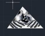
There is a block of a truck with cargo, which partially drove into the hangar. It is required to hide the part of the block that is inside the hangar. Blowing up a block and manually cutting off everything inside the building is a rather painstaking task, and it will be very inconvenient to work with such an object later.
Select a block. Go to tab "Insert" tapes, panel "Link" and choose a team Clip (_CLIP)

The command line will prompt:
Please note that the option <Новый> is selected as the default (triangular brackets indicate this), it suits us, so we just press SPACE or ENTER.
Next, we will be asked what exactly we want to use as a clipping path - an existing polyline, polygonal or rectangular area. We have the option Rectangular- note that it is offered as a default, so we just press again SPACE or ENTER.
Then we need to specify the first corner of the block area that we want to keep, and then the second corner - this is done two consecutive clicks of the left mouse button (LMB):

This is the result we get:

The clipping was successful, but we see a clipping path, which we do not need in this case. To control clipping paths, you need to select one of three options for displaying paths in the ribbon:

Let's choose an item Hide Outlines. Now the result really suits us:

I draw your attention to the fact that when a block is selected, the contours will be highlighted, and moreover, they are interactive - i.e. you can change them by moving the corresponding markers and the cropping result will change, which is quite convenient:

Example #2. Trimming an array with tiles along the contour of the room
In this example, we will consider a very useful case for those who are engaged in interior design, and in particular, tile layout in AutoCAD. The description will be less detailed, because. We have already covered the basics in the first example, but here I will focus only on those steps that will differ.
So, we have a bathroom wall, the tiles in which are laid out using a Rectangular Array:

As you can see, the array goes beyond the wall, and moreover, you need to make a slot under the door. We do not want to blow up the array and cut it off, and this will not work, because the pattern uses hatching.
The beginning will be as in example No. 1 - select the array, call the command Undercut, press SPACE or ENTER to create New outline pruning. But this time we choose the option Polygonal:
Now we need with a few clicks sequentially indicate all the points of our contour and after specifying the last point press SPACE or ENTER:

In total, 8 points were obtained, and the cropping result is presented below:

Agree, very simple and convenient.
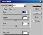
Example #3. Creating your own hatching (texture) from a block
We have this detail:

The part is made of timber and this view is the end face of this very timber. We want to apply a texture to the end, which would resemble the growth rings of a tree and would simplify the visual perception of the part. To do this, create a block of concentric circles, something like this.
Computer-aided design systems - CAD
Working in AutoCAD
Tutorial
2.2.2. Deleting Individual Drawing Objects with the Erase Tool
Now we will consider an example of creating the same drawing, but in relative polar coordinates. However, you must first delete the previously created drawing objects. To do this, you can use the already familiar command Erase in mode All, however, this time we will look at methods of using the tool Erase to delete individual drawing objects.
1. Select the command from the menu system Change? Erase. The pointer will change from a crosshair to a small square called marking pointer. When it appears on the screen, it means that the pointer can be used to select drawing objects. Also pay attention to the command window: it now has a prompt to select objects.
2. Place a marker on one of the lines and click the mouse - the line will change from solid to dotted. This process is called drawing object selection.
Note. In order to make it easier for you to understand which line the marking pointer is on, AutoCAD temporarily highlights it with a thickened outline. In our case, this is not essential, but in complex drawings, this greatly simplifies the task of selecting the desired objects.
3. Do the same with the rest of the lines.
4. Press Enter to complete the selection and apply the command to the selected objects Erase. The quadrilateral you created will be removed from the drawing, and executing the command Erase will end.
Go to Image tab → Crop panel → Create Clipping Path command. Next, you need to select the appropriate sub-parameter (in our case, "Select polyline"). Then select the previously created polyline in the drawing and press Enter.

The clipping path can be inverted by clicking on the little blue arrow, as shown in fig.

To hide the clipping path, set the IMAGEFRAME system variable to "0".
9 "Crop" command in AutoCAD
When constructing, fragments of segments, arcs, etc. are often found that "crawled out" beyond the boundaries of objects. To crop such fragments in AutoCAD, use the "Crop" command. Lines, rectangles, splines, rays, etc. can also be used as clipping elements.
Cropping in AutoCAD is carried out by specifying the so-called cutting edge and a fragment of the object, which, after crossing with this edge, must be removed.
There are several ways to call a command:
On the tab "Home" → Edit panel.
By entering a keyword "OBR" and then press "Enter".

First you need to select the cutting edge (or edges), and then select the objects to be trimmed.
Example. You need to cut off the part of the segment that has gone beyond the rectangle. In this case, the cutting edge will be the rectangle itself, and the cut object will be the part of the segment outside the rectangle. The whole process is shown in the figure.


There can be many cutting edges, as well as cut objects. For example, sometimes all objects or most of them are selected as cutting edges. And then click LMB on those elements that we want to crop. Immediately after specifying the object, it is trimmed. Trimming can be ended by pressing the "Enter" or "Esc" key. Parts of the cutting edges themselves can also be cut objects.


If, when selecting cropped objects, the selection is made with the “Shift” key pressed, then the objects will not be cropped, but lengthened. When selecting cropping objects, you can use the following options:
✗ Line and Sekramka– allow you to select cropped objects using a temporary polyline and a crossing box.


✗ Edge– enables/disables the edge continuation mode up to an imaginary intersection. When enabled, cropping in AutoCAD will also be performed in cases where the cropped object does not clearly intersect with the cutting edge. Whether this mode is enabled or not can be seen from the command line prompt when calling the “Crop” command in AutoCAD.
If it says “Edges = No Continuation”, it means that the mode is off. You can turn it on before selecting cropping objects by entering the letter “C” into the command line (or just from the keyboard).
✗ Cancel- an option that allows you to cancel the trimming of the last object without completely canceling the execution of the entire command.
✗ Delete- this option allows you to delete any objects without interrupting the cutting command. After you use any option, you will again return to specifying the objects to be cropped.
(Finished page 75)
Using bitmaps in AutoCAD drawings is a very common practice. Images can be used as underlays, illustrations, drawing underlays, and more.
An image inserted into a drawing often needs to be trimmed to fit into existing geometry. AutoCAD Standard Tool - Command CUTTING (_XCLIP)- allows you to select a polyline, a polygonal arbitrary contour and a rectangular one as a clipping contour
Result of polygon and rectangle clipping

How to cut around a circle? Obviously, this can be done using a polyline. There are two ways: 1. create a circle from a polyline; 2. create a regular polygon. It will not work to simply draw a circle from two arc segments of a polyline - such a primitive cannot be a contour for trimming.
Round polyline
1. Draw a rectangle of the desired size (recall that the command Rectangle I create a polyline of a special kind)

2. Run the polyline editing command PEDIT (_PEDIT), select our rectangle and select the option Spline

3. Get a rounded spline

4. As a command option CUTTING (_XCLIP) select the resulting spline and you're done!

regular polygon
1. Building POLYGON (_POLYGON) with many sides. How many sides are needed? The question is solved in each specific case - it is necessary that the polygon looks like a circle in appearance. Do not abuse - in most cases, 50-60 sides is enough.

2. As in the previous method, select a polyline as a clipping path and specify our polygon