Automatic voltage regulation in the generator. Generating sets. Main technical characteristics
A generator set is a technical device that is an independent source of electrical energy obtained by burning liquid and gaseous fuels in diesel engines, internal combustion engines and gas turbine plants.
What it is
The generator set consists of an electric generator, the shaft of which is connected to the shaft of the engine, which runs on the appropriate type of fuel (gas, petrol, diesel).
Schematically, a generator set running on gasoline or diesel fuel can be depicted as follows:
Views
Generating sets differ in their design and configuration, installation method and power, as well as other technical characteristics.
By the way of installation, these are:
- Stationary installed - serve as the main or reserve source of electrical energy for objects of various types (industry, housing and communal services, agriculture, etc.). The power of such devices is from 5.0 to several hundred kW.
- Mobile (mobile) - mounted on a special chassis (platform) and can serve as the main and backup source of energy for small energy consumption facilities, as well as in the elimination of emergencies in places where there are no stationary electrical networks. The power of the units of this group of units is from 2.0 to 18.0 kW.
- Portable devices are portable devices used to supply power to a small electrical load. Used as an emergency or backup source energy, power - from 0.5 to 5.0 kW.
Based on the type of fuel used, generating sets are classified as:
- Diesel - when diesel is used. As a rule, these are permanently installed installations, less often - mobile ones. Genset group power of this type, can reach 200 - 300 kW.
- Gasoline - run on low octane gasoline. On mobile installations mounted four-stroke engines, on portable, as a rule - two-stroke. The power of this group is up to 18.0 kW.
- Gas - run on gas, when burned, the gas-piston engine transfers the rotation of its shaft to the shaft of an electric generator that generates an electric current.
These are permanently installed installations that serve as the main source of electrical energy, but can also be used as a backup, if necessary.
By the type of generator used, the installations are subdivided into:
- With an asynchronous electric generator - they have a low cost, but low technical performance. They are installed in low-power plants, usually of a portable or mobile type.
- With a synchronous electric generator - capable of withstanding peak overloads in the electrical networks connected to them, with high quality generated voltage. Installed on powerful diesel generating stations.
Diesel power station
A diesel power plant is a generator set that is equipped with a diesel engine.
The composition of the equipment included in the diesel power plant kit is shown in the following figure:

1 - diesel engine;
2 - electric alternator;
3 - base, frame or frame on which all elements of the power plant are attached;
4 - electrical cabinet, which is a power plant control and protection unit;
5 - tank for storing diesel fuel;
6 - storage battery for starting the diesel engine;
7 - cooling unit, consisting of a radiator and a fan. In the radiator, the circulating fluid is cooled by the fan of the shaft-mounted main diesel engine.
8 - exhaust pipe, which provides exhaust gases removal;
9 - clutch providing connection between the engine shaft and the electric generator shaft.
Have different models diesel power plants, the engine can be started in a different way than in the above diagram. For these purposes, a starting motor ("launcher") running on gasoline or a kick-starter driven by the service personnel can be used.
The couplings that connect the engine shaft to the generator shaft must have a high damping capacity, be collapsible and elastic with non-metallic elements for connecting the half couplings (with a rubber sprocket, with an intermediate disc, a toroidal shell).
Main technical characteristics
The main, general technical characteristics that determine the parameters of operation and the possibility of using diesel power plants are:
- The electrical power delivered by the generator is measured in kW;
- Shaft speed, measured in revolutions per minute;
- Electrical power factor (cos φ);
- The number of phases generated by the electric current;
- Voltage generated by current (220/380 V);
- The frequency of the generated current (50 Hz);
- Fuel consumption per hour of operation;
- Fuel tank volume;
- Weight;
- Dimensions.
In addition to general technical characteristics, the power plant passport contains specifications diesel engine and electric generator, which are, for:
- Engine:
- Engine model;
- Manufacturing company;
- The number of cylinders and their location;
- Cylinder diameter, measured in mm;
- Piston stroke, measured in mm;
- Cooling system type;
- Rated speed of the motor shaft;
- Rated power at rated engine speed;
- Specific fuel consumption, measured in g / kW * hour;
- Engine weight.
- Generator model;
- Manufacturing company;
- Rated voltage at the generator output terminals;
- Efficiency at full load;
- Power factor (cos φ);
- Rated shaft speed;
- Apparent electrical power, measured in kVA;
- Generator weight.
In order for a diesel power plant, which is a complex technical device, to work for a long time and not cause trouble for users, it is necessary to carry out its maintenance on time.

Maintenance can be classified as:
- Daily routine inspections are carried out before the power plant is put into operation.
- Periodic preventive examinations - carried out in accordance with an individual schedule determined for each specific model diesel power plant.
- Technical work, the frequency of which depends on the operating hours of the installation and in accordance with the schedule for their implementation.
During daily inspections or, in the cyclical operation of the power plant, at its start-up, the following is performed:
- Checking the integrity of components and assemblies;
- Checking oil and coolant levels;
- Checking the oil pressure in the engine lubrication system.
During periodic inspections, the following is performed:
- Checking and eliminating malfunctions of units and systems that ensure the operation of a diesel engine. Adjust them if necessary.
- Testing the operation of the electric generator, if necessary - adjusting.
- Checking the insulation resistance of electrical wires and other elements of electrical circuits.
- Functional check electrical devices systems of protection, automation and start-up of power units.
When performing a routine Maintenance work is performed, determined by the manufacturer of the installation, for each specific type of service (TO1, TO2, etc.).
Maintenance is carried out on the basis of its execution schedules and in accordance with the list of works to be performed.
Each power plant maintenance corresponds to a certain number of hours worked by it.
In the cyclical operation of diesel power plants, it is necessary to carry out periodic testing of their operation, which should be performed at least once a month.
Anyone technical device there are advantages and disadvantages, this fully applies to diesel power plants.

So, the advantages of using installations of this type include:
- Significant electrical power compared to gasoline counterparts.
- The ability to stabilize the generated voltage, thereby ensuring its quality indicators, regardless of peak loads when starting electric motors and other electrical devices.
- High efficiency.
- Ability to work in a continuous cycle for a long time without compromising performance.
- Relatively low noise level when generating electrical energy.
- Ability to work in a wide temperature range of ambient air.
- Maintainability and relatively low maintenance costs.
- Large mass of installations and significant overall dimensions.
- For the installation of high-power models, a special base (frame) or foundation is required to ensure the strength of the fastening of the structural elements and their further safe operation.
- The need to monitor the quality of the fuel used, depending on the season (ambient temperature).
- With an incomplete load (below 40.0%), there is a significant wear of units and mechanisms, which leads to the need to perform additional maintenance and, as a result, to financial costs.
- High installation cost.
The generator voltage regulator relay is an integral part of the electrical system of any car. With its help, the voltage is maintained within a certain range of values. In this article, you will learn about what regulator designs exist on this moment, including mechanisms that have not been used for a long time will be considered.
Basic automatic regulation processes
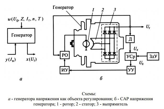
It doesn't matter what type of generator set is used in the car. In any case, it has a regulator in its design. The automatic voltage regulation system allows maintaining a certain value of the parameter, regardless of the frequency with which the generator rotor rotates. The figure shows the generator voltage regulator relay, its diagram and appearance.
By analyzing the physical foundations with which a generator set operates, it can be concluded that the output voltage increases as the rotor speed becomes higher. It can also be concluded that voltage regulation is carried out by decreasing the current supplied to the rotor winding when the rotation speed is increased.

What is a generator
Any car generator consists of several parts:
1. A rotor with an excitation winding, around which an electromagnetic field is created during operation.
2. A stator with three windings connected according to the "star" scheme (alternating voltage is removed from them in the range from 12 to 30 volts).
3. In addition, the design includes a three-phase rectifier consisting of six semiconductor diodes. It is worth noting that the voltage regulator relay of the VAZ 2107 generator in the injection system) is the same.
But the generator will not be able to work without a voltage regulator. The reason for this is the voltage change in a very wide range. Therefore, it is necessary to use an automatic control system. It consists of a comparison device, a control, an executive, a master and a special sensor. The main element is the regulatory body. It can be both electrical and mechanical.

Generator operation
When the rotor starts rotating, some voltage appears at the output of the generator. And it is fed to the excitation winding by means of a regulator. It is also worth noting that the generator set output is directly connected to the battery. Therefore, the voltage is constantly present on the excitation winding. As the rotor speed increases, the voltage at the output of the generator set begins to change. The voltage regulator relay of the Valeo generator or any other manufacturer is connected to the generator output.
In this case, the sensor catches the change, sends a signal to the comparator, which analyzes it, comparing it with a given parameter. Further, the signal goes to the control device, from which it is fed to the Regulator, which is able to reduce the value of the current that is supplied to the rotor winding. As a result, the voltage at the output of the generator set is reduced. Similarly, the above parameter is increased in the case of a decrease in the rotor speed.
Two-level regulators
The two-level automatic control system consists of a generator, a rectifier element, and a storage battery. It is based on an electric magnet, its winding is connected to the sensor. The drivers in these types of mechanisms are very simple. These are ordinary springs. A small lever is used as a comparison device. It is mobile and makes commutation. The contact group is the executive device. The regulator is a constant resistance. Such a generator voltage regulator relay, the circuit of which is given in the article, is very often used in technology, although it is morally outdated.

Two-level regulator operation
When the generator is operating, a voltage appears at the output, which is supplied to the winding of the electromagnetic relay. In this case, a magnetic field arises, with its help the lever arm is attracted. The latter is acted upon by a spring, it is used as a comparison device. If the voltage becomes higher than it should be, the contacts of the electromagnetic relay open. In this case, a constant resistance is included in the circuit. A lower current is supplied to the field winding. The voltage regulator relay of the VAZ 21099 generator and other cars of domestic and foreign production works according to a similar principle. If the voltage at the output decreases, then the contacts are closed, while the current strength changes upward.
Electronic regulator
Two-level mechanical voltage regulators have a big drawback - excessive wear of the elements. For this reason, instead of an electromagnetic relay, they began to use semiconductor elements operating in a key mode. The principle of operation is the same, only mechanical elements are replaced by electronic ones. The sensing element is made on which consists of permanent resistors. A Zener diode is used as a master.
The modern relay-voltage regulator of the VAZ 21099 generator is a more advanced device, reliable and durable. The executive part of the control device functions on the transistors. As the voltage at the generator output changes, the electronic key closes or opens the circuit, if necessary, connect an additional resistance. It is worth noting that the two-level regulators are imperfect devices. It is better to use more modern designs instead.

Three-level regulation system
The quality of regulation of such designs is much higher than that of those considered earlier. Previously, mechanical designs were used, but non-contact devices are more common today. All elements used in this system are the same as those discussed above. But the principle of operation is slightly different. First, voltage is supplied by means of a divider to a special circuit in which information is processed. It is permissible to install such a relay-generator voltage regulator (Ford Sierra can also be equipped with similar equipment) on any car, if you know the device and wiring diagram.
Here the actual value is compared with the minimum and maximum values. If the voltage deviates from the value that is set, then a certain signal appears. It is called the mismatch signal. With its help, the current flowing to the excitation winding is regulated. The difference from a two-level system is that there are several additional resistances.

Modern voltage regulation systems
If the relay-voltage regulator of the generator of the Chinese scooter is two-level, then more advanced devices are used on expensive cars. Multilevel control systems can contain 3, 4, 5 or more additional resistances. There are also automatic control tracking systems. In some designs, it is possible to dispense with the use of additional resistances.
Instead, the frequency of operation of the electronic key increases. It is simply impossible to use circuits with an electromagnetic relay in servo control systems. One of the latest developments is a multi-level control system that uses frequency modulation. In such designs, additional resistances are required, which serve to control the logic elements.

How to remove the relay regulator
It is quite simple to remove the generator voltage regulator relay ("Lanos" or the domestic "nine" you have - it does not matter). It is worth noting that when replacing the voltage regulator, you only need one tool - a flat or Phillips screwdriver. It is not necessary to remove the generator or belt and its drive. Most of the devices are located on the back cover of the generator, and are combined into a single unit with a brush mechanism. The most common breakdowns occur in several cases.
First, when the graphite brushes are completely erased. Secondly, upon breakdown of a semiconductor element. How to check the regulator will be described below. When removing, you will need to disconnect the battery. Disconnect the wire that connects the voltage regulator to the generator output. By unscrewing both fastening bolts, you can pull out the device body. But the voltage regulator relay has an outdated design - it is mounted in the engine compartment, separately from the brush assembly.

Device check
The relay-voltage regulator of the VAZ 2106 generator is checked, "kopecks", foreign cars are the same. Once removed, look at the brushes - they should be more than 5 millimeters long. In the event that this parameter is different, you need to replace the device. To carry out diagnostics, a constant voltage source is required. It is desirable to be able to change the output characteristic. A battery and a pair of AA batteries can be used as a power source. You also need a lamp, it must work from 12 volts. A voltmeter can be used instead. Connect the plus from the power supply to the voltage regulator connector.

Accordingly, connect the negative contact to the common plate of the device. Connect a light bulb or voltmeter with brushes. In this state, a voltage should be present between the brushes if 12-13 volts are supplied to the input. But if you apply more than 15 volts to the input, there should be no voltage between the brushes. This is a sign that the device is working properly. And it does not matter at all whether the voltage regulator relay of the VAZ 2107 generator or another car is diagnosed. If the control lamp is on at any voltage value or does not light up at all, then there is a malfunction of the unit.

conclusions
In the electrical system of the car, the voltage regulator relay of the Bosch generator (as, indeed, of any other company) plays a very important role. Monitor its condition as often as possible, check for damage and defects. Cases of failure of such a device are not uncommon. In this case, in the best case, the battery will be discharged. And at worst, the supply voltage in the on-board network may increase. This will lead to the failure of most of the electricity consumers. In addition, the generator itself may be damaged. And its repair will cost a tidy sum, and if you take into account that the battery will fail very quickly, the costs are quite cosmic. It is also worth noting that the Bosch generator voltage regulator relay is one of the leaders in sales. It has high reliability and durability, and the characteristics are as stable as possible.
Malfunctions of a car's electrical equipment are very common and occupy one of the leading places in the list of breakdowns. They can be conditionally divided into faults of current sources (batteries, generators) and faults of consumers (optics, ignition, climate, etc.). The main the car's power sources are batteries and generators... Failure of each of them leads to a general malfunction of the car and its operation in abnormal modes, or even to immobilization of the car.
In the electrical equipment of a car, the battery and the generator work in inseparable tandem. If one fails, the other will fail after a while. For example, it leads to an increase in the charging current of the generator. And this entails a malfunction of the rectifier (diode bridge). In turn, when supplied from the generator, the charging current may increase, which will inevitably lead to systematic recharging of the battery, "boiling away" of the electrolyte and rapid destruction.
Common generator malfunctions:
- wear or damage to the pulley;
- wear of current-collecting brushes;
- collector wear (slip rings);
- damage to the voltage regulator;
- closure of the turns of the stator winding;
- wear or destruction of the bearing;
- damage to the rectifier (diode bridge);
- damage to the charging circuit wires.
Common battery malfunctions:
- short circuit of the electrodes / plates of the battery;
- mechanical or chemical damage to the battery plates;
- violation of the tightness of the battery cans - cracks in the battery case as a result of impacts or improper installation;
- chemical The main reasons for these malfunctions are:
- gross violations of operating rules;
- expiration of the product's service life;
- various manufacturing defects.
Of course, the design of a generator is more complex than a storage battery. It is quite reasonable that there are many times more generator malfunctions, and their diagnosis is much more difficult.
It is very useful for a motorist to know the main causes of generator malfunctions, ways to eliminate them, as well as preventive measures to prevent breakdowns.
All generators are subdivided into generators variable and direct current... Modern light vehicles are equipped with alternators with a built-in diode bridge (rectifier). The latter is necessary to convert current into direct current, which is used by the car's electrical consumers. The rectifier, as a rule, is located in the cover or housing of the generator and is one piece with the latter.

All electrical appliances of the car are designed for a strictly defined range of operating voltage currents. As a rule, operating voltages are in the range of 13.8-14.7 V. Due to the fact that the generator is "tied" by a belt to the engine crankshaft, from different revolutions and vehicle speed, it will work differently... It is for smoothing and regulating the output current that the voltage regulator relay is intended, which plays the role of a stabilizer and prevents both surges and dips of the operating voltage. Modern generators are equipped with built-in integrated voltage regulators, in common parlance referred to as "chocolate" or "pill".
It is already clear that any generator is a rather complex unit, extremely important for any car.
Types of generator faults
Due to the fact that any generator is an electromechanical device, respectively, there will be two types of malfunctions - mechanical and electrical.
The first include the destruction of fasteners, housing, malfunction of bearings, hold-down springs, belt drive and others not related to the electrical part of the breakdown.
Electrical faults include winding breaks, diode bridge faults, brush burnout / wear, turn-to-turn short circuits, breakdowns, rotor beatings, and relay-regulator faults.

Often, symptoms that indicate a characteristic faulty generator may appear due to completely different problems. As an example, a poor contact in the fuse socket of the generator field winding circuit will indicate a malfunction of the generator. The same suspicion may arise due to burnt contacts in the ignition switch housing. Also, the constant burning of the generator malfunction indicator lamp can be caused by a breakdown of the relay, the blinking of this switching lamp may indicate a generator malfunction.
The main symptoms of a malfunction of the autogenerator:
- When the engine is running, the indicator lamp for battery discharge flashes (or is continuously on).
- Discharge or recharge (boil-off) of the battery.
- Dim car headlights, rattling or low beeps when the engine is running.
- Significant change in the brightness of the headlights with an increase in the number of revolutions. This can be permissible when increasing the speed (overgassing) from idle, but the headlights, having lit up brightly, should not increase their brightness further, remaining at the same intensity.
- Extraneous sounds (howl, squeak) emanating from the generator.
The tension and general condition of the drive belt should be checked regularly. If cracks or delamination occurs, immediate replacement is required.
Alternator repair kits
To eliminate the indicated malfunctions of the generator, it will be necessary to carry out repairs. When you start looking for a generator repair kit on the Internet, prepare yourself to be disappointed - the kits offered usually contain washers, bolts and nuts. And sometimes it is possible to return the generator to working capacity only by replacing - brushes, diode bridge, regulator ... Therefore, a brave man who decides to repair makes an individual repair kit from those parts that fit his generator. It looks something like the table below, using the example of a pair of generators for the VAZ 2110 and Ford Focus 2.
Generator VAZ 2110 - KZATE 9402.3701-03 for 80 A. It is used on VAZ 2110-2112 and their modifications after 05.2004, as well as on VAZ-2170 Lada-Priora and modifications
Generator Renault Logan - Bosch 0 986 041 850 at 98 A. Applies to Renault: Megane, Scenic, Laguna, Sandero, Clio, Grand Scenic, Kangoo, as well as Dacia: Logan.
Troubleshooting
On modern cars, using the "old-fashioned" method by throwing off the battery terminal can lead to serious damage to many electronic systems car. Significant voltage fluctuations in the car's on-board network can damage almost all on-board electronics. That is why modern generators are always checked only by measuring the voltage in the network or diagnosing the removed unit itself at a special stand. First, the voltage at the battery terminals is measured, the engine is started and readings are taken while the engine is running. Before starting, the voltage should be about 12 V, after starting - from 13.8 to 14.7 V. A deviation to a large side indicates that you are "overcharging", which implies a malfunction of the relay-regulator, to a smaller one - that no current is supplied. The lack of recharging current indicates generator malfunctions or chains.
Causes of breakdowns
Common causes of generator malfunctions- this is trivial wear and tear. Almost all mechanical failures, be it brush wear or broken bearings, are the result of long service life. Modern generators are equipped with sealed (non-serviceable) bearings that simply need to be replaced after a certain period or vehicle mileage. The same applies to the electrical part - often the entire assemblies must be replaced.
Also, the reasons may be:
- poor quality of manufacturing of components;
- violation of the rules of operation or work outside the limits of normal modes;
- external factors (salt, liquids, high temperature, road "chemicals", dirt).
Generator self check
The easiest way is to check the fuse. If it is serviceable and its location. Check the free rotation of the rotor, the integrity of the belt, wires, housing. If nothing aroused suspicion, the brushes and slip rings are checked. In the process of operation, the brushes inevitably wear out, they can jam, warp, and the grooves of the slip rings become clogged with graphite dust. A clear sign of this is excessive sparking.
Cases of complete wear or breakdown of both bearings and stator breakdown are not uncommon.


The most common mechanical generator problem is bearing wear. A symptom of this malfunction is a howl or whistle when the unit is operating. Of course, the bearings must be replaced immediately after inspecting the seats. Attenuation can also cause poor generator performance. One of the signs may be a high-pitched whistle from under the hood when the car accelerates or accelerates.
To check the rotor field winding for short-circuited turns or breaks, you need to connect a multimeter, switched to resistance measurement mode, to both slip rings of the generator. Normal resistance is 1.8 to 5 ohms. The reading below indicates the presence of a short circuit in the turns; above - a straight winding break.
To check the stator winding for "breakdown to ground", they must be disconnected from the rectifier unit. With resistance readings issued by a multimeter, having an infinite great importance there is no doubt that there is no contact between the stator windings and the body ("ground").
A multimeter is used to check the diodes in the rectifier unit (after completely disconnecting from the stator windings). Test mode - "diode test". The positive probe is connected to the positive or negative of the rectifier, and the negative to the phase terminal. After that, the probes are swapped. If at the same time the values of the multimeter readings are very different from the previous ones, the diode is working, if they do not differ, it is faulty. Another sign indicating the imminent "demise" of the diode bridge of the generator is oxidation of the contacts, and the reason for this is overheating of the radiator.

Repair and troubleshooting
Everything mechanical problems are eliminated by replacing faulty assemblies and parts(brushes, belt, bearings, etc.) for new or serviceable ones. On older generators, slip ring grooving is often required. Drive belts change due to wear, maximum elongation or expiration. Damaged rotor or stator windings, they are currently being replaced with new assembled ones. Rewinding, although it is found among the services of auto repairmen, is less and less often - it is expensive and impractical.


And that's all electrical problems with a generator you need decide due to verification like others chain elements(in particular the battery), so and directly its details and output voltage. One of the frequent problems that car owners have to face is overcharge, or vice versa, low voltage generator... Checking and replacing the voltage regulator or diode bridge will help to eliminate the first malfunction, and it will be a little more difficult to figure out the low voltage output. There may be several reasons why the generator produces a low voltage:
- increased load on the on-board network by consumers;
- breakdown of one of the diodes on the diode bridge;
- failure of the voltage regulator;
- slippage of the V-ribbed belt (due to weak tension)
- poor contact of the ground wire on the generator;
- short circuit;
- a drained battery.
Many people know about such a device as a generator voltage regulator, but not everyone is able to say what principles underlie its operation and how diagnostics can be carried out. It should be noted that this device is extremely important, because it stabilizes the voltage at the generator output. Imagine how the engine works while driving. Its revolutions are constantly changing, and in a wide range, ranging from 700-900 rpm, and ending with five, seven or even ten thousand. As a result, the generator rotor speed also varies over a wide range. And at any value of the revolutions, a stable voltage must be maintained, which will be enough to charge the battery. If there are any defects, then a thorough check of the generator voltage regulator is required.
Mechanical voltage regulators
The history of the automotive industry has more than a hundred years, during which time many designs have been invented and implemented that improve the performance of all units. Among them is a relay-regulator, since a modern machine cannot work normally without it. Initially, mechanical devices were used, which were based on an electromagnetic relay. For example, the voltage regulator of the VAZ generator of the first models was just like that.
He, as it turned out later, has no advantages, quite often disadvantages. Moreover, the main disadvantage is low reliability due to the fact that there are moving contacts. They are erased over time, since the device works constantly, without interruption. In addition, sometimes it is necessary to carry out adjustment work, which does not have a very good effect on the operation of the car. Modernity dictates the rule according to which the machine must be serviced in a timely manner in service centers. And the driver does not have to be able to carry out complex repairs, only the ability to drive a car and change a wheel is required from him (this is the maximum).
Electronic relay regulators
For the reasons stated above, electronic type voltage regulators are widely used. Progress does not stand in one place, therefore key transistors, triacs, thyristors have replaced the electromagnetic relay. They have a very high reliability, since there are no mechanical contacts, instead of which there is a semiconductor crystal. Of course, the technology for the production of such devices must be thought out. Otherwise, the semiconductor may fail. It is quite simple to check the voltage regulator of a generator of this type, you just need to take into account its features.

When compared with the previous, mechanical type of relay-regulators, one can see one feature - electronic ones are produced in the same housing with brushes. This saves space and, most importantly, makes replacement and diagnostics easier. A special feature of electronic types is the accuracy of voltage regulation. The properties of the semiconductor do not change during operation. Therefore, the voltage at the generator output will always be the same. But it is worth talking about the way of regulation, about how the whole process is going on. And it is quite interesting, you will have to consider in general terms the design of the generator.
What are the elements of a car generator

The base is the housing, otherwise it is called the stator. It is a stationary part of any electrical machine. There is a winding in the stator. In automotive generators, it has three parts. The thing is that a three-phase alternating voltage is generated at the output, its value is about 30 volts. The reason for using this design is to reduce ripple, since the phases overlap each other, as a result, a direct current appears after the rectifier. Six semiconductor diodes are used to convert the voltage. They have one-way conductivity. If a breakdown occurs, then it is quite simple to determine it using a tester.
But there will be no voltage at the output of the stator winding, if one condition is not taken into account - a magnetic field is needed, and a moving one. It is not difficult to make it, it is enough to wind the winding on a metal anchor and supply power to it. But now the question arises about voltage stabilization. It makes no sense to do this at the output, since the elements will be required very powerful, because the currents are large. But here one feature of electric machines comes to the aid of designers - if a stabilized voltage is applied to the rotor winding, then the magnetic field will not change. Consequently, the voltage at the generator output is also stabilized. The VAZ 2107 generator also works, the voltage regulator of which operates on the same principles as that of the "dozen".
Voltage Regulator Components

Modern cars are equipped with fairly simple designs. They are non-separable, two elements are combined in one housing - the regulator itself and the graphite brushes, which transmit the supply voltage to the rotor winding of the generator. Moreover, electronic types of devices can be of two types. For example, the voltage regulator of the VAZ-2110 generator produced in the late 90s was made on a small circuit board. Modern devices are made using a single semiconductor crystal, which contains all the elements. You can even say that it is a small microcircuit.
Graphite brushes are connected to the terminals of a circuit board or semiconductor element. Voltage is supplied to them from the storage battery through a lamp, which is necessary for diagnosing the generator. Please note that you cannot put LED elements instead of it, since they have no internal resistance. Roughly speaking, an incandescent lamp also works as a fuse. If the thread burns out, then the voltage supply to the rotor winding stops, the generator stops working. If the lamp lights up, then there is a breakdown. Either the brushes are worn out, or the belt is torn, but sometimes it also happens that the semiconductor diodes in the rectifier fail. In this case, it is necessary to replace the generator voltage regulator with a new one.
How to remove the regulator
If the malfunction is only in the voltage regulator, then there is little work to replace it. A special tool is also required - one screwdriver is enough. It is not necessary to completely disassemble the generator, since the brushes with the voltage regulator are located on its back cover.

You don't even need to loosen the belt. It is necessary to remove the voltage regulator of the 2110 generator in two cases:
- The brushes are completely worn out.
- A breakdown has occurred in the semiconductor.
The options for checking the device will be presented below. First, disconnect the battery. The fact is that a power wire goes from it to the generator, there is no protection on it, because it is used to charge the battery. And the current consumption of this circuit is very high. There is one connector on the regulator body, disconnect the wire from it. Now you can unscrew the two mounting bolts. After that, the generator voltage regulator can be easily removed from the back cover... It's time to check it out.
Voltage regulator diagnostics
First of all, pay attention to the condition of the brushes - if their length is less than 0.5 cm, then it is necessary to change the assembly assembly. It’s not worth reinventing the wheel. There is no point in soldering new brushes, since reliability will only suffer from this. Since there are several ways to check the generator voltage regulator, it is worth starting with the most difficult thing - with the removal of the device. For diagnostics, you need a power supply, at the output of which the voltage can be changed in the range of 10-18 volts.

You also need an incandescent lamp. Its electrical parameters are as follows: supply voltage - 12 volts, power - 2-3 watts. Serve food as follows:
- Positive terminal to the connector in the regulator body (it is the only one on new samples).
- Minus the total plate.
The incandescent lamp turns on between the two brushes. The procedure is as follows:
- When a voltage of 12-12.5 volts is applied, the incandescent lamp should be on.
- At a voltage over 15 Volts, it should go out.
If it lights up at any supply voltage, or does not light up in any of these cases, then there is a breakdown of the regulator and it needs to be replaced.
How to make a diagnosis without removing it?

It is not recommended to carry out such a check, since there is no way to assess the condition of the brush assembly. But the cases are different, so even such a diagnosis can bear fruit. To work, you need a multimeter or, if there is none, an incandescent lamp. The main thing for you is to measure the voltage in the car's on-board network, to determine if there are any surges. But they can be noticed while driving. For example, the blinking of a light when the engine speed changes.
But measurements made using a multimeter or voltmeter with an extended scale will be more accurate. Start the engine and turn on the low beam. Connect a multimeter to the battery terminals. The voltage should not exceed 14.8 volts. But it is also impossible for it to fall below 12. If it is not in the permitted range, then there is a breakdown of the voltage regulator. It is possible that the contacts at the points of connection of the device with the generator are broken, or the contacts of the wires are oxidized.
Regulator circuit modernization

How full the battery will be charged directly depends on the voltage regulator. Unfortunately, simple designs described above have a large scatter of parameters. Therefore, having bought three copies of the same devices in one store, you will receive different output voltages. And this is a fact, no one will argue. If the battery does not have enough charging, then it will lose its capacity in a short time. And it will not be able to start the engine. It will only need to be restored with a stationary charger.
But you can install a three-level generator voltage regulator, which allows you to change the characteristics by simply switching the toggle switch. Its circuit contains two semiconductors, which have slightly different characteristics. Due to this, it becomes possible to adjust the output voltage. When one semiconductor is turned on, 14.5 volts appear at the output, and if the other is put into the circuit, it will be slightly higher. The use of such a device is relevant in the winter period, when the battery capacity decreases and additional charging is required.
How do I install a three-level regulator?

You will need a small set of tools for this procedure. You need a screwdriver, heat shrinkable insulation, self-tapping screws, it is possible that a drill with a 2-4 mm drill will be needed. So, everything is in order. The first step is to remove the two bolts holding the brush assembly and regulator. In its place you need to put a new one that comes with the kit. It differs from the simple one in that there are only brushes, the semiconductors are located in a separate block. You need to place the second node near the generator, on the car body.
To do this, make small holes for fastening. It is worth noting that the block with semiconductors needs additional cooling. Therefore, it will be necessary to install it on an aluminum radiator, only after that make fasteners to the body elements. If sufficient cooling is not provided, then the device may malfunction, as well as disruption of its operation - the regulation will not occur correctly. After completing the fastening work, connect the two nodes with wires, conduct insulation. It is advisable to fasten the connecting wires with cable ties to the existing bundles.
Can I make my own three-level regulator?
If you are familiar with radio engineering, you can find a cathode and an anode on the diode, then it will not be difficult for you to make such a device yourself. The question is, does it make sense. You will need two Schottky diodes to make. If you have them, then the price of the construction will be scanty. But if you have to buy them (and it is not known at what price), then you can compare the costs with the cost of a ready-made three-tier regulator. The three-level type generator voltage regulator circuit is simple, anyone who knows how to handle a soldering iron can repeat it.

To implement your idea, you will also need a plastic case. You can also use aluminum, it will even be better, since the cooling will be more efficient. It is only advisable to cover all surfaces with a layer of insulation so that the contacts do not close to the body when driving. You will also need to install a switch that will switch the semiconductor elements. Works on installing the device on a car are similar to those described in the previous paragraph. It is also worth noting that you still need to purchase a brush assembly.
conclusions

Do not neglect a device such as a car alternator voltage regulator. The service life of the battery depends on its quality and condition. And if there are any defects in the device, then it must be replaced. Monitor the condition of this element, if necessary, clean the contacts so that failures do not appear. The generator is located at the bottom of the engine compartment, and if there is no mudguard, then a lot of water and dirt gets on it in bad weather. And this leads to the appearance of defects, and not only in the voltage regulator, but even in the stator and rotor windings. Therefore, for the normal functioning of all systems, car care is required. And before you check the generator voltage regulator, conduct a thorough inspection and clean all structural elements from contamination.
Thousands of people around the world are engaged in repairs every day. When performing it, everyone begins to think about the subtleties that accompany the repair: in what colors choose wallpaper, how to choose curtains in the color of the wallpaper, arrange furniture correctly to obtain a uniform style of the room. But rarely does anyone think about the most important thing, and this is the main thing to replace the electrical wiring in the apartment. After all, if something happens to the old wiring, then the apartment will lose all its attractiveness and become completely unsuitable for life.
Any electrician knows how to replace the wiring in an apartment, but any ordinary citizen can do this, however, when performing this type of work, he should choose high-quality materials in order to get a safe electrical network in the room.
The first action to be taken is plan future wiring... At this stage, you need to determine exactly where the wires will be laid. Also, at this stage, you can make any adjustments to the existing network, which will make it possible to arrange the lamps and in the most comfortable way in accordance with the needs of the owners.
12.12.2019
Narrow-branch devices of the knitted sub-industry and their maintenance
To determine the extensibility of hosiery, a device is used, the diagram of which is shown in Fig. 1.
The design of the device is based on the principle of automatic balancing of the rocker arm by the elastic forces of the test product acting at a constant speed.
The weight rocker is an equal-armed round steel rod 6 with an axis of rotation 7. On its right end, legs or a sliding form of the track 9 are attached to its right end using a bayonet lock, on which the product is put on. A suspension for loads 4 is pivotally attached to the left shoulder, and its end ends with an arrow 5 showing the equilibrium state of the rocker arm. Before testing the product, the rocker arm is brought into equilibrium with a movable weight 8.

Rice. 1. Diagram of the device for measuring the extensibility of hosiery: 1 - guide, 2 - left ruler, 3 - engine, 4 - suspension for loads; 5, 10 - arrows, 6 - rod, 7 - axis of rotation, 8 - weight, 9 - track shape, 11 - tension arm,
12 - carriage, 13 - lead screw, 14 - right ruler; 15, 16 - helical gears, 17 - worm gear, 18 - coupling, 19 - electric motor
To move the carriage 12 with the stretching lever 11, a lead screw 13 is used, at the lower end of which a helical gear 15 is fixed; through it, the rotational movement is transmitted to the lead screw. The change in the direction of rotation of the screw depends on the change in rotation 19, which is connected to the worm gear 17 by means of a coupling 18. A helical gear 16 is mounted on the gear shaft, which directly imparts movement to the gear 15.
11.12.2019
In pneumatic actuators, the adjustment force is generated by the action of compressed air on the diaphragm, or piston. Accordingly, the mechanisms are diaphragm, piston and bellows. They are designed to position and move the control valve gate in accordance with a pneumatic command signal. The full working stroke of the output element of the mechanisms is carried out when the command signal changes from 0.02 MPa (0.2 kg / cm 2) to 0.1 MPa (1 kg / cm 2). The limiting pressure of compressed air in the working cavity is 0.25 MPa (2.5 kg / cm 2).
For diaphragm linear thrust mechanisms, the rod reciprocates. Depending on the direction of movement of the output element, they are subdivided into mechanisms of direct action (with an increase in membrane pressure) and reverse action.

Rice. 1. The design of the direct-acting diaphragm actuator: 1, 3 - covers, 2 - membrane, 4 - support disc, 5 - bracket, 6 - spring, 7 - stem, 8 - support ring, 9 - adjusting nut, 10 - connecting nut
The main structural elements of the diaphragm actuator are a diaphragm pneumatic chamber with an arm and a moving part.
The diaphragm pneumatic chamber of the direct-acting mechanism (Fig. 1) consists of covers 3 and 1 and membrane 2. Cover 3 and membrane 2 form a sealed working cavity, cover 1 is attached to the bracket 5. The movable part includes support disk 4, to which the membrane is attached 2, a rod 7 with a connecting nut 10 and a spring 6. The spring at one end abuts against the support disk 4, and the other end through the support ring 8 into the adjusting nut 9, which serves to change the initial tension of the spring and the direction of movement of the rod.
08.12.2019
Today there are several types of lamps for. Each has its own pros and cons. Consider the types of lamps that are most often used for lighting in a residential building or apartment.

The first type of lamps - incandescent lamp... This is the cheapest type of lamp. The advantages of such lamps include its cost, simplicity of the device. The light from these lamps is the best for the eyes. The disadvantages of such lamps include a low service life and a large number of consumed electricity.
The next type of lamps - energy-saving lamps... Such lamps can be found for absolutely any type of base. They are an elongated tube in which there is a special gas. It is the gas that creates the visible glow. Modern energy saving lamps, the tube can have a wide variety of shapes. The advantages of such lamps: low power consumption compared to incandescent lamps, daylight, a large selection of socles. The disadvantages of such lamps include the complexity of the design and flicker. The flickering is usually subtle, but the eyes will get tired of the light.
28.11.2019
Cable assembly- a kind of mounting assembly. The cable assembly consists of several local ones, terminated on both sides in an electrical installation shop and tied into a bundle. The installation of the cable route is carried out by laying the cable assembly into the cable route fastening device (Fig. 1).
Ship cable route- an electric line mounted on a ship from cables (cable bundles), cable routing fixing devices, sealing devices, etc. (Fig. 2).
On the ship, the cable route is located in hard-to-reach places (along the sides, ceiling and bulkheads); they have up to six turns in three planes (Fig. 3). On large ships, the maximum cable length reaches 300 m, and the maximum cross-sectional area of the cable route is 780 cm 2. On individual ships with a total cable length of over 400 km, cable corridors are provided for placing the cable route.
Cable routes and cables passing through them are subdivided into local and trunk routes, depending on the absence (presence) of sealing devices.
Trunk cable routes are subdivided into routes with end boxes and pass-through boxes, depending on the type of use of the cable box. It makes sense for the selection of technological equipment and cable routing technology.
21.11.2019
In the field of development and production of instrumentation and automation devices, the American company Fluke Corporation occupies one of the leading positions in the world. It was founded in 1948 and since that time has been constantly developing and improving technologies in the field of diagnostics, testing, analysis.
Innovation from an American developer
Professional measuring equipment from a multinational corporation is used for servicing heating, air conditioning and ventilation systems, refrigeration units, checking air quality, calibrating electrical parameters. The Fluke brand store offers to purchase certified equipment from an American developer. Full the lineup includes:- thermal imagers, insulation resistance testers;
- digital multimeters;
- analyzers of the quality of electrical energy;
- rangefinders, vibrometers, oscilloscopes;
- calibrators of temperature, pressure and multifunctional apparatus;
- visual pyrometers and thermometers.
07.11.2019
A level gauge is used to determine the level of different types of liquids in open and closed storages and vessels. It is used to measure the level of a substance or the distance to it.
To measure the liquid level, sensors are used that differ in type: radar, microwave (or waveguide), radiation, electrical (or capacitive), mechanical, hydrostatic, acoustic.