Decoders. Decoders Binary to seven-segment code decoder
A seven-segment display is often used to display decimal and hexadecimal digits. An image of a seven-segment indicator and the names of its segments are shown in Figure 3.
Figure 3.3 Image of a seven-segment indicator and the name of its segments.
To display the number 0 on such an indicator, it is enough to light segments a, b, c, d, e, f. To display the number "1", segments b and c are lit. In exactly the same way, you can obtain images of all other decimal or hexadecimal digits. All combinations of such images are called a seven-segment code.
Let's create a truth table for a decoder that will allow you to convert a binary code into a seven-segment one. Let the segments ignite at zero potential. Then the truth table of the seven-segment decoder will take the form shown in Table 3.2. The specific value of the signals at the output of the decoder depends on the connection diagram of the indicator segments to the output of the microcircuit. We will look at these diagrams later, in the chapter on displaying various types information.
Table 3.2. Truth table of a seven-segment decoder.
| Inputs | Exits | |||||||||
| a | b | c | d | e | f | g | ||||
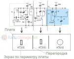
In accordance with the principles of constructing a circuit using an arbitrary truth table, we obtain a schematic diagram of a seven-segment decoder (decoder) that implements the truth table given in Table 2. This time we will not describe in detail the process of developing the circuit. Received circuit diagram seven-segment decoder is shown in Figure 3.4.

Figure 3.4. Schematic diagram of a seven-segment decoder (decoder).
To facilitate understanding of the principles of operation of the circuit at the output of logical elements "AND", the numbers of the truth table rows implemented by them are shown.
For example, at the output of segment a, a logical one will appear only when a combination of binary signals 0001 (1) and 0100 (4) is applied to the input. This is accomplished by combining the corresponding circuits with the “2OR” element. At the output of segment b, a logical one will appear only when a combination of binary signals 0101 (5) and 0110 (6) is applied to the input, and so on.
Currently, seven-segment decoders are produced in the form of separate microcircuits or are used in the form of ready-made blocks as part of other microcircuits. The graphical designation of the seven-segment decoder microcircuit is shown in Figure 3.5.
Decoders, like encoders, convert one code at their input into another code, which is supplied to the output. One of the special cases of using a decoder is its collaboration with seven-segment indicator. Typically, a decoder converts a binary number into a signal at one of its outputs, but for this particular case, special decoders are used that convert the binary code at its input into a seven-segment indicator code at the output. Job of this type Let's consider devices using the example of the K514ID2 microcircuit.
This microcircuit has four inputs D1-D4, and seven outputs: a, b, c, d, e, f, g, for connection to the corresponding segments of the seven-segment indicator. Pin R - operation permission; in order for the decoder to respond to signals at its inputs, pin R must have a high logical level.
It should be especially noted that power is supplied to output 14 of the K514ID2 microcircuit, common wire 6. Power is supplied from a stabilized 5V power supply.
We will supply counting pulses from a multivibrator; they will be counted by a counter with a non-binary conversion factor, to the outputs of which a decoder of a seven-segment indicator is connected.

This electrical circuit diagram turns out to be quite complex, therefore, even when assembled correctly, it sometimes refuses to work correctly due to the abundance of solderless pin connections. As they say, electronics is the science of contacts. Many problems in electrical engineering and electronics come down to the fact that there is a contact where it is not necessary or there is no contact where it is necessary.

Experience has shown that application in laboratory work Seven-segment indicators produced by the industry are unjustified due to the fact that such indicators have insufficient “student resistance”; if connected incorrectly, they quickly fail. Therefore, modules were developed that simulate the operation of seven-segment indicators based on AL307B LEDs. For this reason, the numbers on the indicator look somewhat unusual, but general principle The operation of the seven-segment indicator is quite clear.


Video
Literature
- https://kiloom.ru/spravochnik-radiodetalej/microsxema/k514id2-kr514id2.html
- http://ru.pc-history.com/mikrosxema-k514id2.html
- https://eandc.ru/pdf/mikroskhema/k514id2.pdf
- Yampolsky V.S. Fundamentals of automation and electronic computer technology - M. Prosveshchenie, 1991
- http://site/publ/nachinajushhim/multivibrator_na_ehlementakh_i_ne/5-1-0-1366
- http://site/publ/nachinajushhim/schetchik_na_mikroskheme/5-1-0-1372
- http://site/publ/nachinajushhim/samodelnye_moduli_dlja_izuchenija_mikroskhem/5-1-0-1352
A seven-segment code is necessary to display the values of numbers from 0 to 9 on digital indicators. Seven-segment, because the numbers are displayed in so-called segments, of which there are seven. Below is a table of the correspondence between binary and seven-segment codes.
| Number | Binary code | Seven segment code | |||||||||
| a | b | c | d | e | f | g | |||||
Wow, damn it. Well, in general, I won’t show you logic. Since the counter is already sign, let's look at how it works together with the decoder. The scheme is real, that is, it can be repeated.
As you can see, there is nothing complicated, all the elements of the circuit are for us familiar . A clock pulse generator is assembled on elements DD1.1, DD1.2 (K561LA7). Resistor R1 and capacitor C1 set the pulse repetition rate. I don’t remember the formula for determining the repetition rate, but I’ll remember and write it down. It is possible, if not impossible, to determine this very frequency using the “scientific poke” method. In any case, if you plug in a variable one instead of a constant one, the frequency can be adjusted within certain limits. From the output of the generator, pulses are sent to a counter located on DD2. This is a reversible binary decimal counter with preset. Input ±1 determines the counting direction, input 2/10 - mode (binary or decimal). Input V is intended to allow writing to the status counter of information inputs D0 - D3. This particular counter (561IE14, 564IE14) needs to be set to a log level. 1. Resik R2 and conder C2 form a differentiating chain. When the power is turned on, a short pulse at input V, generated by a differentiating circuit, allows writing to the status counter of inputs D0 - D3. Since these pins are connected to the common wire, 0000 is written to the counter, i.e. it is reset to zero. The clock generator generates pulses, the counter counts them, and from its outputs 1-2-4-8 the counting result is sent to the input of the decoder DD3 (514ID1). This is a binary to seven segment code decoder. From the outputs of the decoder, the signals (according to the second table) go to the inputs of the seven-segment indicator HL1, which displays this information, i.e. a series of numbers from 0 to 9. Inside the DD3 mikruhi there is a DC. This is from the bourgeoisie Decoder - decoder in our language. At the transfer output p (pin 7) of counter DD2, when it overflows, a signal is generated. If we take the following nodes: DD2, DD3, HL1 and stick them at the bottom of the DD2 counter, similarly connect the corresponding inputs, except C, connect the transfer output (pin 7) of the previous counter to the C input of the next one, we will get a multi-valued indicator. After the first counter counts 10 pulses, the second one will switch to 1. After the next 10 pulses, the second counter will increase by another 1 and so on. This principle of frequency division is used by, for example, clocks. The only thing is that the conversion factor is different (not 10, but 6), after all, there are 60 seconds in a minute. This counter can also be made to count up to 6. Take the log. element AND, its inputs are connected to outputs 2-4 (pins 11 and 14), and the output is connected to the differentiating chain R2C2. Then, when the number 6 (0110) is reached, the level is log. 1 at the output of element AND will generate, not without the help of the R2C2 circuit, a pulse that will be recorded in the counter 0000. And also, by increasing the frequency of the generator, the numbers will run faster, for example like this:

Multiplexer is a device that samples one of several inputs and connects it to its output, depending on the state of the binary code. In other words, a multiplexer is a signal switch controlled by a binary code and having several inputs and one output. The input whose number corresponds to the binary code is connected to the output. Well, a fancy definition: multiplexer is a device that converts parallel code into serial code.
The structure of a multiplexer can be represented various schemes, but in my opinion this one is more understandable:

Rice. 1 - Multiplexer structure
The biggest crap is nothing more than an AND-OR element. Specifically, here is a 4-input element. Well, the squares with ones inside, if anyone doesn’t remember, are inverters. Let's look at the conclusions. Those on the left, namely D0-D3, are called information inputs. They serve something for them. The inputs in the middle, namely A0-A1, are called address inputs. This is where the binary code is supplied, on which it depends which of the inputs D0-D3 will be connected to the output, designated Y in this diagram. Input C, God knows, why is it here. It seems like a work permit, or maybe just for show off. Well, off to the bathhouse. The diagram also has address inputs with inversion. So they are also shown here for show off. This figure shows a four-input, or as it is also called, 4X1 multiplexer. Therefore, there are only 2 address inputs. As we know, the maximum number of variables is defined as 2 n, where n is the code digit. Here we see that there are four variables, which means the digit will be equal to 2 (2 2 = 4). To explain the principle of operation of this circuit, let's look at the truth plate:
| A1 | A0 | Y |
| D0 | ||
| D1 | ||
| D2 | ||
| D3 |
This is how binary code selects required input. That is, if we have four objects, well, let’s say, they send signals, and we have one display device. We take a cartoon (multiplexer) and insert it into the circuit. Depending on the binary code, a signal from the desired object. Here's a really bad example.
The cartoon is designated by a microcircuit like this:

Rice. 2 - Multiplexer
In general, there are a lot of multiplexers of all kinds. There are also dual four-input, eight-input, 16-input, quad two-input, etc. The one in the picture is made from a flashlight.
Demultiplexer. A demultiplexer is the inverse device of a multiplexer. That is, the demultiplexer has one input and a bunch of outputs. The binary code determines which output will be connected to the input. In other words, a demultiplexer is a device that samples one of several outputs and connects it to its input or, it is a signal switch controlled by a binary code and has one input and several outputs. The output whose number corresponds to the state of the binary code is connected to the input. And a fancy definition: demultiplexer is a device that converts serial code into parallel.
Typically used as a demultiplexer decryptors binary code into positional code, in which an additional gating input is introduced. Due to the similarity of the structures of the multiplexer and demultiplexer in CMOS series there are microcircuits that are simultaneously a multiplexer and a demultiplexer, depending on which side the signals are supplied from, for example, K561KP1, which works as an 8x1 switch and a 1x8 switch (that is, as a multiplexer and demultiplexer with eight inputs or exits). In addition, in CMOS chips, in addition to switching digital signals(log. 0 or 1) it is possible to switch analogue. In other words, it's a switch analog signals, controlled by a digital code. Such microcircuits are called switches. For example, using a switch you can switch the signals entering the amplifier input (input selector). Finally, we will look at a simple circuit of the UMZCH input selector. Let's build it, let's say, using flip-flops and a multiplexer.

Rice. 3 - Input selector
Here is such a simple scheme. So, let's look at the work and details. On the triggers of the DD1 microcircuit, a ring counter button presses with 2 digits (two triggers - 2 digits). Two-digit binary code goes to the address inputs D0-D1 of the DD2 chip. The DD2 chip is a dual four-channel switch. In accordance with the binary code, inputs A0-A3 and B0-B3 are connected to the outputs of the microcircuit A and B, respectively. Elements R1, R2, C1 eliminate bouncing of the button contacts. Differentiation chain R3C2 sets the flip-flops to zero when power is turned on, with the first input connected to the output. When you press the button, trigger DD1.1 switches to the log state. 1 and the second input is connected to the output, etc. The inputs are enumerated in a ring, starting from the first.
On the one hand it’s simple, on the other it’s a little inconvenient. God knows how many times the button was pressed after turning it on and which input is connected to the output. It would be nice to have an indicator for the connected input. This is where it comes in handy seven-segment decoder. We click the link, remember the seven-segment decoder and look at the diagram (where the numbers run). We take the decoder and indicator, cut off the counter and other nonsense, transfer the decoder with the indicator to the switch circuit and connect the first two inputs of the decoder (in the diagram as DD3), i.e. 1 and 2 (pins 7 and 1) to the direct outputs of the triggers DD1.1 DD1.2 (pins 1 and 13). We throw decoder inputs 4 and 8 (pins 2 and 6) onto the case (i.e., we apply logic 0). All! The indicator will show the state of the ring counter, namely numbers from 0 to 3. Number 0 corresponds to the first input, 1 to the 2nd, etc.
Register(from bourgeois to register - to register) is a digital node designed to record and store numbers. Some registers can convert information from serial to parallel form and vice versa. First, let's look at the storage register.
In this article we will talk about digital display.
Seven-segment LED indicators are designed to display Arabic numerals from 0 to 9 (Fig. 1).
Such indicators are single-digit, which display only one number, but there may be more seven-segment groups combined into one housing (multi-digit). In this case, the numbers are separated by a decimal point (Fig. 2)

Fig.2.
The indicator is called seven-segment due to the fact that the displayed symbol is built from seven separate segments. Inside the housing of such an indicator there are LEDs, each of which illuminates its own segment.
It is problematic to display letters and other symbols on such indicators, so 16-segment indicators are used for these purposes.
LED indicators come in two types.
In the first of them, all cathodes, i.e. the negative terminals of all LEDs are combined together and a corresponding terminal is allocated for them on the case.
The remaining terminals of the indicator are connected to the anode of each LED (Fig. 3, a). This circuit is called a “common cathode circuit.”
There are also indicators in which the LEDs of each segment are connected according to a circuit with a common anode (Fig. 3, b).

Fig.3.
Each segment is designated by a corresponding letter. Figure 4 shows their location. 
Fig.4.
As an example, consider a two-digit seven-segment indicator GND-5622As-21 red. By the way, there are other colors, depending on the model.
Using a three-volt battery, you can turn on segments, and if you combine a group of pins into a bunch and apply power to them, you can even display numbers. But this method is inconvenient, so shift registers and decoders are used to control seven-segment indicators. Also, often, the indicator pins are connected directly to the microcontroller outputs, but only when indicators with low current consumption are used. Figure 5 shows a fragment of a circuit using PIC16F876A.

Fig.5.
To control the seven-segment indicator, the K176ID2 decoder is often used.
This chip is capable of converting binary code consisting of zeros and ones into decimal digits from 0 to 9.
To understand how it all works, you need to collect simple diagram(Fig. 6). The K176ID2 decoder is housed in a DIP16 package. It has 7 output pins (pins 9 - 15), each dedicated to a specific segment. Point control is not provided here. The microcircuit also has 4 inputs (pins 2 - 5) for supplying binary code. The 16th and 8th pins are supplied with plus and minus power, respectively. The remaining three conclusions are auxiliary, I will talk about them a little later.

Fig.6.
DD1 - K176ID2
R1 - R4 (10 - 100 kOhm)
HG1 - GND-5622As-21
There are 4 toggle switches in the circuit (any buttons are possible), when you press them, a logical one is supplied to the decoder inputs from the power supply plus. By the way, the microcircuit itself is powered with a voltage of 3 to 15 Volts. IN in this example the entire circuit is powered by a 9-volt "crown".
There are also 4 resistors in the circuit. These are so-called pull-up resistors. They are needed to guarantee at the logical input low level, when there is no signal. Without them, the readings on the indicator may not be displayed correctly. It is recommended to use the sameresistance from 10 kOhm to 100 kOhm.
In the diagram, pins 2 and 7 of the HG1 indicator are not connected. If you connect the DP pin to the minus power supply, the decimal point will light up. And if you apply a minus to the Dig.2 output, then the second group of segments will also light up (will show the same symbol).
The decoder inputs are designed in such a way that to display the numbers 1, 2, 4 and 8 on the indicator, you only need to press one button (the layout has toggle switches corresponding to inputs D0, D1, D2 and D3). If there is no signal, the number zero is displayed. When a signal is applied to input D0, the number 1 is displayed. And so on. To display other numbers, you need to press a combination of toggle switches. Table 1 will tell us which ones we need to press.

Table 1.
To display the number "3" you need to apply a logical one to the input D0 and D1. If you apply a signal to D0 and D2, the number “5” will be displayed(Fig. 6).

Fig.6.
Here is an extended table in which we see not only the expected figure, but also those segments (a - g) that will make up this figure.

Table 2.
The 1st, 6th and 7th pins of the microcircuit are auxiliary (S, M, K, respectively).
In the diagram (Fig. 6), the 6th pin “M” is grounded (to the power supply minus) and there is a positive voltage at the output of the microcircuit for working with an indicator with a common cathode. If an indicator with a common anode is used, then one should be applied to the 6th pin.
If a logical one is applied to the 7th pin “K”, then the indicator sign is extinguished, zero allows the indication. In the scheme this conclusion grounded (to the power supply minus).
A logical unit (plus power) is supplied to the first output of the decoder, which allows the converted code to be displayed on the indicator. But if you apply a logical zero to this pin (S), the inputs will stop receiving a signal, and the current displayed sign will freeze on the indicator.
One interesting thing to note is that we know that toggle switch D0 turns on the number "1", and toggle switch D1 turns on the number "2". If you press both toggle switches, the number 3 will be displayed (1+2=3). And in other cases, the indicator displays the sum of the numbers that make up this combination. We come to the conclusion that the decoder inputs are arranged thoughtfully and have very logical combinations.
You can also watch the video for this article.
Seven-segment indicator: programming operation
In the first part of the article, a description was given of the indicator and how to connect it to the microcontroller. In the second and third parts, we will sequentially go through all the stages of organizing the operation of a microcontroller with an indicator and creating a program, the result of which will be a really working design.
Converting the binary code of a decimal number into the code of a seven-segment indicator
Let's look again at the diagram for connecting a seven-segment indicator to a microcontroller: 
In this diagram port pins PB0…..PB7 connected to the indicator terminals in a certain sequence. Pin PB0 corresponds to segment “A” and then, accordingly, according to the serial number of the port pin and according to the alphabet of the indicator pins, while the decimal point “dp” is connected to port pin PB7. Now and further we will consider connection diagrams for indicators with a common cathode, and if necessary, I will insert additions for an indicator with a common anode.
In order to highlight a certain number on the indicator, it is necessary to install logical one

In the figure above, black numbers from 0 to 7 are port pins, green Latin letters are LED indicator pins, red zeros are logical levels at the port outputs (in this case, logical level “0”). In order, for example, to highlight the number “4” on the indicator and light the decimal point, we need to apply logical 1 to the indicator pins B, C, F, G and dp, which corresponds to applying a logical 1 to port pins 1,2,5 ,6 and 7:

Therefore, the first thing we need to do is determine the correspondence of each decimal digit binary number, which must be output to the output of the microcontroller port to light the corresponding indicator segments.
For the “four” we have already defined the following combination = 1110 0110, which corresponds to the hexadecimal number 66h, we also define for the remaining digits:

The operation we performed is called binary code translation decimal number into the seven-segment indicator code .
This table is given for seven-segment indicators with a common cathode (the indicator segment lights up at logic level “1”). For indicators with a common anode (the indicator segment lights up at the logical level “0”), the binary codes must be inverted (change 0 to 1, and vice versa) and recalculate the corresponding values in the hexadecimal system.
Programming a one-digit seven-segment indicator
The use of a single-digit indicator in the design may be required in different cases. For example, we are assembling a combination lock and there is a need to display the number corresponding to the pressed button, or in a security alarm to display the number of the triggered sensor. So the scope of application of single-digit indicators is decent.
We will organize the display of numbers on a single-digit indicator in the form of a subroutine: “Output of information to a single-digit seven-segment led indicator»
, so that this subroutine can then be used in any program with minimal changes.
Subroutine algorithm:
1. Initialization of the indicator (subroutine)
— setting the port to which the indicator is connected to output information
— recording seven-segment indicator codes corresponding to decimal digits in certain memory cells
This subroutine must be called separately from the main program
2. Entering the main subroutine
3. Main part
- read the current digit
— determine which code of the seven-segment indicator corresponds to the current decimal digit
— write a specific indicator code to the microcontroller port
4. Exit the subroutine
To design a program in the form of a subroutine, we need to do a number of actions:
1.
We assign a name to the indicator initialization subroutine - Ini_Indicator_1(For example)
2.
We assign a name to the main subroutine - Indicator_1
3.
We assign names to SRAM variables in which the codes of the seven-segment indicator will be stored, for example:
— D0(for the number 0, and so on), D1, D2, D3, D4, D5, D6, D7, D8, D9
- assign the name of the variable in which the address of the memory cell (D0) with the code of the first digit (0) will be stored - D0_9
4.
We assign the name of the variable that will store the current digit that needs to be displayed on the indicator. The main program will write the calculated data (numbers) into this variable, which we display on the indicator - Data(For example).
Here's how, for example, in Algorithm Builder (other examples are also for this program), the names of variables in program memory (RAM, SRAM) are declared:
The “Name” column lists all variable names. In the “Adress” column, the entry “@D0_9” means that the variable D0_9 stores the address of the first variable (D0)
Indicator initialization subroutine (the subroutine is called from the main program before calling the subroutine for outputting information to the indicator):

Now let's look at the main part of the program and decipher it:

The main program wrote to the variable we assigned Data the current digit (for example, the digit 6 ) and called the subroutine to display it on the indicator Indicator_1.
Subroutine operation:
— Variable contents Data written to the working register R20, now in the register number 6(working register can be any)
— Let's say the first variable with a digit code 0
we have it in the memory cell at the address 100
. In fact, we do not know the addresses of memory cells where values are stored D0…D9, but they follow each other exactly. Therefore the variable was assigned D0_9, which, as we have assigned, stores the address of the memory cell D0(V this moment address = 100
).
— With the following command:
@D0_9 —> Y we load in double register Y variable address D0 and we get that in the register Y the number was written down - 100
.
— With the following command:
Y+R20 we add the number 100
with number 6
, result = 106
it is stored in double register Y.
— With the following command:
[Y] —> R20 we write the contents of a memory cell located at an address that is written in a double register Y (106), and at this address we have a variable memory cell located D6. Now in working register R20 number written down 7Dh — seven-segment indicator code for displaying number 6
.
— With the following command:
R20 -> PortB we display the contents R20 to the port P.B. — highlight the number 6
— Returning from the subroutine