LISP Programs. How to insert an image in AutoCAD? How to install the application in AutoCAD
Examples of LISP programs will be posted on this page. For many of them there are lessons with a detailed description of the code.
If you know how to run in AutoCAD, you can immediately
How to use the program.
All programs are written for use in the full version of AutoCAD. They will not work in AutoCAD LT.
If you liked any program on this site and you want to install it on your computer. To do this, you need to do the following:
1. Download the program to your computer;
2. All programs are archived. Therefore, after you have downloaded the archive, you need to unzip it. Unzipping the archive, you will receive program files that can be stored anywhere on your computer (I use the folder D: \\ MyLisp for this);
3. The program files must be loaded into AutoCAD;
4. Run new commands that are stored in the downloaded files.
I think that everyone will cope with the first two points. Therefore, we’ll immediately talk about loading LISP files into AutoCAD.
Download LISP files to AutoCAD.
There are several ways to upload a program to AutoCAD LISP. I will describe some of them.
Download files using the “Download / Upload applications” window.
Open AutoCAD. On the ribbon, go to the "Management" tab and click on the "Application" button. See Fig. 1.
Fig. 1 Application Button
If you are working in Classic AutoCAD mode:
In the main menu, select "Service", then click on the line "Applications ...". See Fig. 2.

Fig. 2. The line "Application
Find the folder in which the file is located, select it and click on the "Download" button. See Fig. 3.

A message appears at the bottom of the window stating that the selected file has been downloaded. Please note that this way you can download not only LISP files (* .lsp), but also other applications supported by AutoCAD ( * .arx; * .crx; * .dvd; * .dbx; * .vlx; * .fas).
In this way, programs are downloaded for temporary use. After you close AutoCAD and then open it again, they will not be in AutoCAD, and to use them you need to download them again.
In order for you to need LISP files downloaded to AutoCAD automatically, you need to add them to the automatic download list. To do this, click on the briefcase “” (or on the “” button. See. Fig. 4.

The "Add file to automatic startup list" window opens. We find the desired folder, select the file and click on the "Open" button. See Fig. 5.
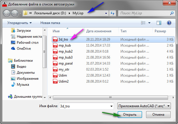
Fig. 5. Adding a file to the automatic startup list
Which will be automatically loaded at each start of AutoCAD.
After you add all the necessary files, click on the “Close” button. Then click on the “Close” button in the “Download / Unload Applications” window. See Fig. 6.

Fig. 6. File added
Keep in mind that files will be downloaded automatically only at the next start of AutoCAD. If you want to use them in the current session, you need to download them in the manner described above (or in any other way).
Download files using the Visual LISP Editor.
Open the Visual LISP Editor:
Type VLIDE (or VLISP) at the command prompt and press
Or, on the ribbon, go to the "Management" tab and click on the "Visual LISP Editor" button. See Fig. 7.
Fig. 7. Visual LISP Editor
The Visual LISP Editor opens. Click on the “Open File” button. The “Open file for editing / viewing” window will appear.
Find the desired folder;
Highlight the file and click on the "Open" button. See Fig. 8.
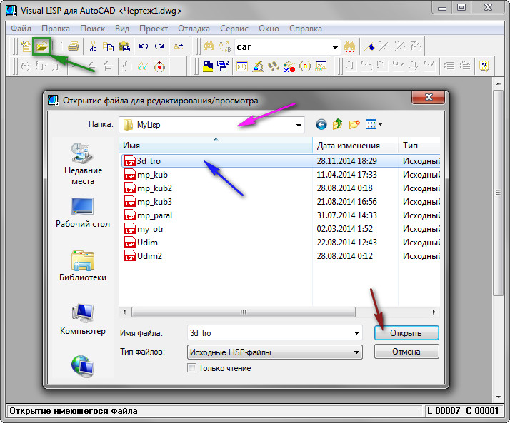
Fig. 9. Opening a file in the Visual LISP Editor
The file is loaded into the active editor window. To load it into AutoCAD, you need to click on the button " Download active editor window».
This method has its advantages associated with the fact that you see the program code of the file:
1. You can see how many commands are in this LISP file (there can be several).
2. Find the names of these commands: find the line with the defun function; The name of the team is immediately after c: (in our case it is: 3d_tro and roY);
3. Among other things, you have the opportunity to edit the program code.
See Fig. 9.
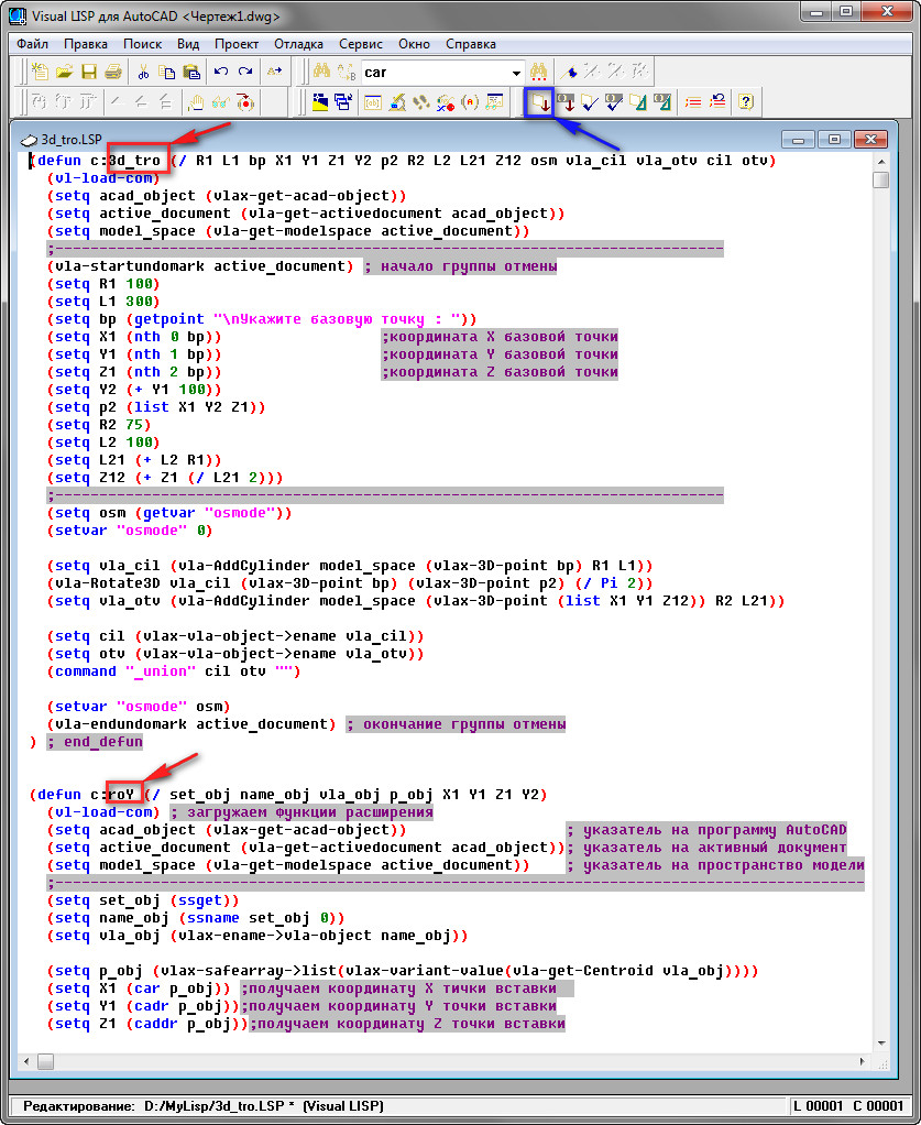
Fig. 9. Names of new teams.
To define the boundaries of a command in program code, place the mouse cursor in front of the defun function opening bracket and double-click the left mouse button. The defun function that describes one command is to stand out. See Fig. 10.

Fig. 10. The program code of one command
Launch new teams.
After the files are downloaded, we can run new commands in AutoCAD that are stored in these files. To do this, just type the TEAM NAME on the command line and press
In addition, for any team, you can create a button.
Place it on the toolbar and place the panel on the tape.
After that, run the command by clicking on this button.
Read how to do this in the lessons: "" and "".
You can also create hot keys for these commands and launch them by pressing certain keys on the keyboard.
How to do this, read in the lesson: "".
Of course, we did not understand all the ways to download files and run commands, but this is more fully enough to comfortably use the ones below.
List of LISP programs.
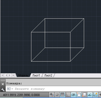
LISP program "mp_kub.lsp"
A program that draws in AutoCAD a cube with sides of 200.
The name MP_KUB is used to run in AutoCAD
Specify a base point».
Specify any point in the AutoCAD working window. The team will build a cube with sides of 200.

(File size: 449 bytes)
LISP program "mp_paral.lsp"
The program draws a parallelogram with the sides indicated in the dialog box. The program only works with the mp_paral.dcl dialog box file. Therefore, you need to download two files.
For AutoCAD to locate the dialog box file, it must be placed in the AutoCAD auxiliary files folder.
See how to do this in the lesson: "".
Or in the program code, in the line
(setq dcl_id (load_dialog "mp_paral.dcl")) you need to specify the full path to the dialog box file.
For example, if the file is located in the “D: \\ MyLisp” folder, the line should look like this:
(setq dcl_id (load_dialog "D: \\\\ MyLisp \\\\ mp_paral.dcl"))
The name MP_PARAL is used to run in AutoCAD
After starting, a dialog box will appear on the screen.
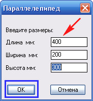
You need to specify the dimensions of the sides of the parallelogram and click on the OK button.
Specify any point in the AutoCAD working window. The team will build a parallelogram with the sides indicated in the dialog box.
For a detailed description of the program code, see the lesson: "".
For a detailed description of the code for creating a dialog box, see the lesson: "".
(File size: 392 bytes)
(File size: 781 bytes)
LISP program "Sum_dl.lsp"
The program considers the sum of the lengths of the selected segments. In the process of selecting segments AutoCAD gives the number of selected segments and the sum of their lengths.
To run in AutoCAD, use the name SumDl
Choose a line»:
Indicate any segment.
He will stand out. A message appears on the command line that one line is selected and its length.
Choose a line»:
Specify the next segment.
He will stand out. A message appears on the command line about the number of selected segments and their total length.
The following request appears again: " Choose a line»:

The number of selected segments and their total length.
And so on to infinity. To end the program, press
For a detailed description of the program code, see the lesson: "".
(File size: 464 bytes)
LISP program "Sum_dls.lsp"
The program of the sum of lengths with a free choice of segments.
The program considers the sum of the lengths of the selected segments.
The selection of segments can be done one at a time and in a group using a frame (or using a secant frame). In general, by any standard AutoCAD method.
To run in AutoCAD, use the name: SumDls
Select objects»:
You can select segments in any standard way AutoCAD. If the wrong segment is accidentally selected, its selection can be canceled. To do this, hold down the key
The process of selecting and deselecting segments is displayed on the command line.

Deselect an object.
After you have selected all the necessary objects, click
A message appears on the command line about the number of selected segments and their total length.

For a detailed description of the program code, see the lesson: "".
(File size: 487 bytes)
LISP program "Sum_dlv.lsp"
The program considers the sum of the lengths of the segments throughout the drawing.
To run in AutoCAD, use the name: SumDlv
After starting the program, select all segments in the drawing
A message appears on the command line about the number of segments in the entire drawing and their total length.
The result of the program.
(File size: 440 bytes)
LISP program "Sum_sl.lsp"
The program considers the sum of the lengths of the segments on the selected layer.
To run in AutoCAD, use the name: SumSl
After starting the program issues a request: " Select an object to define the layer: “
Specify any object. The program selects and calculates the length of all segments on the layer on which the specified object is located.
A message appears on the command line about the number of segments on this layer and their total length.

Result when choosing a blue layer.
(File size: 563 bytes)
LISP program "Scom.lsp"
The program shows how the standard AutoCAD commands can be used in AutoLISP program code.
An example is given:
- Build a line.
- Building an arc.
- Using the edit command: Mirror
- Translation of the drawing SW isometric.
- Semiconus constructions.
To run in AutoCAD, use the name: SCOM
After starting, the program issues a request: “ Specify a base point».
Specify any point in the AutoCAD working window. The team will build two segments and an arc. Then it mirrors them. Then he will translate the drawing of the SW to isometry and build the Semiconus.

For a detailed description of the program code, see the lesson: "".
(File size: 535 bytes)
LISP program "mp_kub2.lsp"
The program creates a cube block whose sides are predefined.
The name MP_KUB2 is used to run in AutoCAD
After starting, it issues a request: " Set the side length of the cube:»
A prompt appears: “ Specify a base point».
Specify any point in the AutoCAD working window. The team will build a block in the form of a cube with the sides whose value we set during the first request.

Block cube.
For a detailed description of the program code, see the lesson: "".
(File size: 802 bytes)
LISP program "mp_kub3.lsp"
The program creates a cube block using the AutoLISP language extension functions, the sides of which are predefined. The program calculates the volume of the cube, and the coordinates of the center of the upper face. The volume and coordinates are stored as additional data that can be retrieved at any time.
To run in AutoCAD, use the name: MP_KUB3
After starting the program issues a request: " Set the side length of the cube:»
Enter the numerical value of the side of the cube and click
A prompt appears: “ Specify a base point».
Specify any point in the AutoCAD working window. The team will build a block in the form of a cube with the sides whose value we set during the first request. The program will also calculate the volume and the coordinates of the center of the upper face and save them in the block as additional data.
Block cube.
For a detailed description of the program code, see the lesson: "".
(File size: 993 bytes)
LISP program "Udim.lsp"
The program reads additional data from the block created in the lesson: "". Inserts the dynamic block created in the lesson: "".
See the lesson: “” (or in the lsp program instead of the “Vyn” file name, you will need to specify the full path to it. For example: if the file is in the “D: \\ MyLisp” folder, you need to put “D: \\\\ MyLisp \\ To run in AutoCAD, use the name: UDIM
After starting, the program issues a request: “Select a block:”
The command will insert a leader. A leader will start from the center of the top face. At the top of the shelf will be the name of the specified block, at the bottom - its volume.
Specify the next block.
Download program Udim.lsp
 (File size: 538 bytes) LISP program "Udim2.lsp"
The program reads additional data from the block created in the lesson: "". Inserts the dynamic block created in the lesson: "". Changes the length and position of the extension line and the length and position of the shelf.
In order to see how the program works, you first need to:
Download the mp_kub3.lsp program, and create a block (or several blocks) using it.
- Download the dynamic block “Vyn.dwg”.
- Place "Vyn.dwg" in the AutoCAD auxiliary files folder.
- See the lesson: “” (or in the lsp program instead of the “Vyn” file name, you will need to specify the full path to it. For example: if the file is in the “D: \\ MyLisp” folder, you need to put “D: \\\\ MyLisp \\ To run in AutoCAD, use the name: UDIM2
After starting, the program issues a request: “Select a block:”
Specify a pre-built block (created by mp_kub3.lsp).
{!LANG-d332249fc156c0d416f8200b879741f7!}
{!LANG-226dc9e063962857f7c1f7361888dd85!}
The beginning of the extension line will appear.
You need to specify the second point of the extension line. The command will insert a leader. At the top of the shelf will be the name of the specified block, at the bottom - its volume.
Then the program again asks: “Select a block:”
Specify the cube block again.
On request " Indicate extension line:»
Specify the second point of the line elsewhere.
To the following request “Select a block:” - click
(File size: 856 bytes)
LISP program "3d_tro.lsp"
The program contains two commands
The first team draws a 3D tee in AutoCAD.
To run in AutoCAD, use the name: 3D_TRO
After starting, it prompts: “ Specify a base point».
Specify any point in the AutoCAD working window. The team will build a 3D tee.

Dedicated tee.
The second command rotates the 3D tee 90 degrees around an axis parallel to the Y axis.
To run in AutoCAD, use the name: ROY
Preselect 3D Tee
Type ROY at the command prompt and click
The tee will turn.

Rotated 3D tee.
For a detailed description of the program code, see the lesson: "".
(File size: 927 bytes)
LISP program "3d_bolt.lsp"
The program draws a 3D bolt in AutoCAD.
To run in AutoCAD, use the name: 3D_BOLT
After starting, it prompts: “ Specify a base point».
Specify any point in the AutoCAD working window. The team will build a 3D bolt.

(File size: 1.02 kB)
Good day, dear friends! We continue our series of articles devoted to the most widespread in the world system of computer-aided design of drawings on a computer - program (AutoCAD)!
We hope you already read our previous article on how to download and get a free license for AutoCAD.
And we not only read it, but passed the registration and in front of you looks something like this window of an Internet browser:
If yes, then this means that you have everything you need to install a licensed “AutoCAD”. (If not, carefully read our article: “Where to download AutoCAD? Free license and registration on the site”).
Installing AutoCAD (AutoCAD) in stages:
Well then what? Let's install AutoCAD !!!
Everyone knows that in order to install any program on a computer, you must first download it from the Internet, or purchase an installation disk, or maybe even an installation flash drive.
Until recently, it was exactly the same with AutoCAD, but for today, in the method we are considering for obtaining a licensed student version of AutoCAD, we will single out two installation methods: “Install now!” and “Download first, then install!”
Let's start with the first method, “Install it Now!”
With this method, you both download and install the program at the same time, but first things first.
Having received Serial Number and Product key - you get a license for AutoCAD. And it's time to install it. We are looking for a red button and click it! Moreover, we click on the phrase “INSTALL NOW”.
This will be the easiest way to install AutoCAD when you sign up and request a license. BUT! It is important that you have a good computer / laptop and very good internet access.
If you have access to the Internet 3G or ADSL with low speeds, then you better go to the second method, but what will be written below is better to just briefly get acquainted.
After you click Install now, a small installer file will be downloaded, by running which, you will begin to install AutoCAD 2018. And, ideally, after that you just click “Next” and “Next” ...
There will be a process of parallel downloading the installation files of the program and their subsequent installation on a computer / laptop.
Therefore, it is important that there is good speed and good hardware (well, a good computer should be, not buggy).
The installation window that you will see during the installation process reflects the progress of the operations performed and the amount of downloaded files.
Not only AutoCAD program files will be installed, but also auxiliary programs:


If you have good Internet access at a speed of at least 50 Mbit / s, then the whole process can take about half an hour. But there may be more, since the load on the servers of the AUTODESK company also affects the download speed.
When the installation is complete, you will see a window similar to this:


After clicking on the “Finish” button and starting AutoCAD, the first thing you will encounter is the licensing issue. And it is in the “first case” of the installation that it is solved very simply!
But you must have the Internet. You will see a window where you can read Autodesk's privacy information.
And after clicking the “Accept” button, the license will be automatically checked, and you do not need to do anything. That is, your credentials, the installation program will determine for itself!

Well, after successfully passing the license check (and this is done once! Then the Internet is not needed), you can safely work in the AutoCAD licensed program (AutoCAD).
Once again, this is the easiest and fastest way to download and install the program.
If for some reason you are unable to do this, then go to the second method. It is a little more laborious, but not complicated.
And very complete and informative screenshots will help you figure it out, even just “from the pictures”?.
And so, method number two « First download AutoCAD, then install! ".
We return to the beginning of our process, and instead of the “INSTALL NOW” button, press the small button next to it:
We get a drop-down menu in which we select the item “DOWNLOAD NOW”.

A small Download Manager file will be downloaded (In Russian, autocad downloader?).

We install it, agreeing to the provision of a license and the provision of services.

Then, the Autodesk Download Manager program is installed.

After installation, you again click on the “DOWNLOAD NOW” button and the computer will already offer you to open the link in the installed application.

Then, you indicate where the AutoCAD installation files will be saved and the download process will begin. Download time directly depends on the speed of connection to the Internet.

In my case, the speed indicators were different. From 0 bps to 30 Mb / s and higher. As you can see, initially it shows 25 minutes before the end, then (after 15 seconds) 14 minutes. And even 8 minutes.


But then, the download speed decreased, falling to zero or minimum values. But after a while, the speed returned to normal and the whole process took about 20 minutes.
That is, the second method is suitable for those who have an unstable Internet connection. With Autodesk Download Manager, you can slowly download AutoCAD for at least 24 hours. But although I would not advise you of this ... And I would advise you to read the article to the end and find out a little trick, for those who have poor access to the Internet ?.
After all the files have been downloaded, you will see a window similar to the one presented below.

The installation process has begun!

After initializing the installation program, you will be prompted to install the program. Click the "Install" button!

A window opens with information on licensing the software product, in which you will need to agree with the information on the grant of a license and the provision of services. We put the switch on the item "I accept" and click "Next".

We select the installation folder, or (we would advise) leave everything unchanged and click on the " Install»!

The installation process, similar to the previous one, will begin, but the installation will already take place without downloading the installation files.


After installing all the necessary software modules and additional applications, the process will be completed and, most likely, you will be asked to restart the computer.


After rebooting, we find on the desktop a shortcut to start AutoCAD and go!
Stop, stop, stop ... At least AutoCAD will tell you so. Well, or rather, he will ask for information about the license, for which you boldly press the "central button" "Enter the serial number."


It will go to the program activation window.
Not everyone loves this process, everyone wants to draw / simulate / design as soon as possible, but a smart program first wants to get to know the owners.

Therefore, click the "Activate" button!
After that, the Serial Number and Product key that you were given during registration will come in handy. Did not record? Forgot? Fantastically gone? ?
Once again, go to your account on the website of the Autodesk educational community and update information.
After that, we indicate it in the window, by analogy with the bottom:

The license will be checked, how many times it has been used, what it allows you to do, and so on.

When the activation process is completed, you will see a joyful message: “Congratulations! Activation completed successfully! ”


Well, and lastly, you may be asked about the collection and use of your data. Here, everyone chooses for himself, but we would not recommend sharing information about failures. After all, without this there are a lot of other things.

To summarize ?!
The first method is the fastest, you can do it without even releasing a cup of coffee from your hands.
The second method is less fast, but it is possible to download the installation kit on one flash drive, so that later you can share and simplify downloading the auto cad for those who do not have stable Internet access.
But you need to register on the site! How to get your Serial Number and Product key. Then everything will be easier!
Now let's look at how to implement it in work.
Applications with the following file extension are available for AutoCAD: * .arx, * .crx, * .lsp, * .dvb, * .dbx, * .vlx, * .fas.Consider the example of LISP, which allows you to align the text relative to the specified point on the X or Y axis (download the file "Align Text.lsp").
How to install * .lsp file in AutoCAD?
1. Go to the "Management" tab and in the "Applications" panel, select the "Download Application" command. You can use the command line in AutoCAD and enter "_appload".
2. The "Download / unload applications" dialog box opens, through which you need to find the appropriate file with the extension * .lsp or others, which was listed above.

3. After the done actions click the “Download” button.
4. After a message indicating a successful download appears at the bottom of this dialog box, you can test the installed application. Click the Close button.

How to run lisp application command?
AutoCAD lisp can't see commands. It should be based on the source file that was loaded into the program.
We said earlier that the script file can be opened through the usual Notepad. As a rule, at the very top of this text document, developers leave all the necessary information for work, including the name of the team that will launch LISP. In this example, it is “ z-text-align", So you need to enter just such a request in the command line to call the tool.

How to load lisp in AutoCAD LT?
With a question: “How to install a Lisp in AutoCAD” everything is clear. But, how to load it into similar programs, for example, AutoCAD Electrical / Mechanical?
Unfortunately, AutoLISP applications only run on the full version of AutoCAD. Therefore, such scripts cannot be embedded in AutoCAD LT or other versions.
The process of inserting blocks into a drawing is approximately the same as inserting individual objects. In this case, you can change the scaling or rotate the block to the desired level. You can also develop a dynamic unit with a variety of scaling and angle of rotation of copies. On the blocks of this type we will talk a little after.
How to insert blocks into drawings
To insert a block into a drawing file, you will need to perform the following steps:
- We call the block insert window.
a) enter “Paste” into the command line.
b) execute the command Insert\u003e Block.
c) Click on the corresponding icon in the block panel.
- Select insert block or single file.
a) To insert a block from the working drawing, select the option you want from the "Name" window.
b) Insert the file using the "Browse" option.
3. Set the flag opposite the "Point on screen" option. Assign it to the insertion point, scale and angle of rotation.
- Also put a check in the option "Equal scales".
- And finally, check or uncheck the "Split" function.
- We complete the process by choosing the “OK” option.
- The software will automatically ask you to specify the necessary parameters, if they have not been specified previously:
- Indicate the insertion point, as described in the first lesson, the insertion point coincides with the base point of the block.
- Specify the scale of the inserted block; the default scale is 1: 1. In order to change the scale along the axes, when asked to enter a scale, enter Xon the command line. After which the command will prompt you to enter the scale along the axis X and axis Y. For three-dimensional models, the input of scales along the axes is similar. Specifying a negative scale along one of the axes creates a mirror image relative to the second axis.
- Indicate the angle of rotation by entering the value of the angle in the command line, or by specifying angle points, with the cursor.
When you insert a drawing file, sheet space objects are not included in the insert, in order to insert such objects, you must define them in a block.
How to work with DesignCenter
DesignCenter is an explorer window that helps you select one block from already saved drawings or a library with the ability to preview.
Select the block and insert it into the drawings
- Open DesignCenter and clamp ctrl + 2.
- Specify a direct path to the folder with the desired file using Explorer.
- In the open folder, open the desired drawing.
- So the user will get access to all parameters and attributes.
- Select the block tab.
- We look at a number of icons with blocks of the selected drawing.

To insert a block, you will need to carry out a procedure that occurs by analogy with the one described above.
To insert a block, you can simply drag it onto the open drawing field. The program will automatically prompt the user to edit the drawing. In one drawing, you can insert many blocks of different types, sizes and contents.
We are finishing the lesson on inserting blocks and file systems. Next, we will talk about working with their management and library sections.
There are many variables in any program. They are used in a variety of places and for different purposes. Any object in the drawing also represents a set of variables - coordinates, color, layer, area, etc. And the drawing itself also has a number of properties that can be used to display additional and most importantly relevant information on the drawing. It is for these purposes that AutoCAD uses fields. They allow you to display the text value of various variables in the drawing.
In this article, I will describe some methods of using fields, similar methods can be invented much more, the principle is approximately the same everywhere.
reception 1: Landfill area
Create an auto cad object - a polyline. In my case, it is a rectangle. In the geometric properties of the object (ctrl + 1) we see the value of the area. In order to display it in the drawing, we use the fields. To do this, create a text block and add a field to it:

You can do this in three ways using the button. add field, using hot keys (ctrl + f), or RMB (right mouse button) - add a field
As a result, we get the following picture:

- Field category - in the drop-down list, select - Objects
- Field name select object
- Click on the button to select object (select object)
- Select the desired object in the drawing
- Choose a data output format
- Choose the accuracy with which we will output them.
- Additional Format opens another panel with finer settings.
- We set in additional parameters multiplier (Conversion Factor) for example, to derive the area value not in square millimeters, but in meters. We can also set the prefix, suffix, delimiters (integer / fractional part for example) and suppress extra zeros.
As a result, in the text we will have a field associated with the object selected in the drawing. If we resize the polygon, then the value fields in the text will also change. The truth is not immediately, in order to see the changes it is necessary to “update” the drawing, i.e. execute command _regen.
reception 2: Print out the path to the drawing file
 Adding the path to the drawing file as a whole is similar to the above adding a field from an object in the drawing, only in this case the data source will not be the object in the drawing, but the drawing itself.
- Field Category - Document
- Choose File Name
- Actually everything, you can press OK, or select several of the possible options for formatting the output: lowercase, lowercase (Uppercase), etc.
As you can see with the file path, everything is extremely simple. But you can also notice that in addition to the path, the document has several more properties that few people know about. Namely - the document can be indicated, the author, title, make a description, etc. These properties can be used, in addition, here you can add your own properties, the so-called UDA (user defined attributes)
Add custom properties and fields to an Autocad drawing

Drawing properties can be found in the menu item. File \\ Drawing Properties .. (File \\ Drawing Properties ..)
 In the tab General (Summary)we can see the very properties that we saw in the document properties in the field editor. Accordingly, you can also use these fields. But there are not so many of them, and their names oblige them to be used as intended. But there is good news in the tab Customwe can add as much as we like.
- Select tab Custom
- Press the button Add
- In the window that opens, set Custom Property Name
- In the next line we set Value
When creating properties, you should take into account a small nuance, after adding a property, you will not be able to change its name, only the value. You can change the name only by deleting the old property and creating a new one.
New custom properties will be available in the same tab as the file path:

Other examples of fields in AutoCAD.
This is not an exhaustive list of field examples. So you can apply fields in blocks when they will receive their values \u200b\u200bdirectly from the occurrence of a block in the drawing. You can also get properties not only from an object in a drawing, or a document, but for example from a drawing sheet, or a binder in which this sheet is used.
In addition to this, you can add fields to the table and perform calculations with them. As an option, add the area of \u200b\u200bthe polygons to the table, and calculate the total area using the formula.
Ksati, the fields are not only in the AutoCAD. In a similar form, they exist and can be used in almost all office applications.
Conclusion
Despite some purely technical complexity with the use of fields in the project, their use is extremely important in those cases when you constantly work with more or less similar projects.
However, these difficulties themselves are bypassed with the help of scripts; a number of scripts are given for the automated solution of the problem described in Example 1


