We work with simple timers STM32 F4 discovery. STM32F3. Using a timer Stm32 timer overflow interrupt
We've already looked at the SysTick timer, which is part of the Cortex core. However, it doesn't end there. There are many timers in stm32, and they are different. Depending on the goal, you will have to choose one or another timer:
- SysTick;
- timers general purpose(eng. general purpose timer) - TIM2, TIM3, TIM4, TIM15, TIM16, TIM17;
- advanced timer - TIM1;
- watchdog timer.
The only thing worth mentioning about the latter is that it is designed to control system freezes and is a timer that must be reset periodically. If the timer is not reset within a certain period of time, the watchdog timer will reboot the system (microcontroller).
Timers come in different bit sizes: for example, SysTick is 24-bit, and all the timers that we have in stone are 16-bit (that is, they can count up to 2 16 = 65535), except WatchDog. In addition, each timer has a certain number of channels, that is, in fact, it can work for two, three, etc. These timers can work with incremental encoders, Hall sensors, and can generate PWM (pulse width modulation, English. Pulse Width Modulation - which we'll talk about later) and much more. In addition, they can generate interrupts or make requests to other modules (for example, to DMA - Direct Memory Access) based on various events:
- overflow;
- signal capture (eng. input capture);
- comparison (eng. output compere);
- event trigger.
If everything is clear to us with timer overflow (more precisely, reaching “0”) - we looked at SysTick - then with others possible modes We are not yet familiar with the work. Let's take a closer look at them.
Signal capture
This mode is well suited for measuring the pulse repetition period (or their number, say, per second). When a pulse arrives at the MK output, the timer generates an interrupt from which we can remove the current counter value (from the TIM_CCRx register, where x is the channel number) and save it to an external variable. Then the next impulse will come, and by a simple subtraction operation we will get the “time” between two impulses. You can catch both the leading and trailing edge of a pulse, or even both at once. Why is this necessary? Let's say you have a magnet that you glued to a rim on a wheel, and a Hall sensor to the fork of a bicycle. Then, when you rotate the wheel, you will receive a pulse every time the magnet on the wheel is in the same plane as the Hall sensor. Knowing the distance that the magnet travels per revolution and the time, you can calculate the speed of movement.
There is also a PWM capture mode, however this is more of a special way of setting a timer rather than separate mode operation: one channel catches leading edges, and the second - falling edges. Then the first channel detects the period, and the second - the filling.
Comparison mode
In this mode, the selected timer channel is connected to the corresponding pin, and once the timer reaches a certain value, the pin state will change depending on the mode setting (it can be "1" or "0", or the output state is simply inverted).
PWM generation mode
As the name implies, the timer in this mode generates pulse width modulation. We will talk more about this mode, as well as where it can/should be used, in the next lesson after reviewing signal capture.
Using an advanced timer, you can generate a three-phase PWM, which is very useful for controlling a three-phase motor.
Dead-time mode
Some timers have this feature; it is needed to create delays at the outputs, which are required, for example, to eliminate through currents when controlling power switches.
In the course we will only use “signal capture” and “PWM generation”.
The article describes the timers of 32-bit ARM microcontrollers of the STM32 series from STMicroelectronics. The architecture and composition of the basic timer registers are considered, and practical examples of programs are given.
For any microcontroller, the timer is one of the most important components, which allows you to very accurately count time intervals, count pulses arriving at the inputs, generate internal interrupts, generate signals with pulse width modulation (PWM) and support direct memory access (DMA) processes.
The STM32 microcontroller contains several types of timers that differ from each other in functionality. The first type of timers is the simplest and is Basic Timers. Timers TIM6 and TIM7 belong to this type. These timers are very easy to configure and control using a minimum of registers. They are capable of counting time intervals and generating interrupts when the timer reaches a specified value.
The second type is General-Purpose Timers. This includes timers TIM2 to TIM5 and timers TIM12 to TIM17. They can generate PWM, count pulses arriving at certain pins of the microcontroller, process signals from the encoder, etc.
The third type defines timers with advanced control (Advanced-Control Timer). This type includes the TIM1 timer, which is capable of performing all of the above operations. In addition, based on this timer, you can build a device capable of controlling a three-phase electric drive.
Basic timer device
Let's consider the design and operation of a basic timer, the block diagram of which is shown in the figure. The basic timer is built on the basis of 16-bit registers. Its basis is the counting register TIMx_CNT. (Hereinafter, the symbol “x” replaces the number 6 or 7 for the basic timers TIM6 and TIM7, respectively.) The TIMx_PSC prescaler allows you to adjust the clock frequency for the counter register, and the TIMx_ARR autoload register makes it possible to set the timer counting range . The trigger and synchronization controller, together with the control and status registers, serve to organize the operating mode of the timer and allow you to control its operation.
Thanks to its organization, the timer counter can count forward and backward, as well as to the middle of a given range in the forward direction and then in the reverse direction. The base timer input can be supplied from several sources, including the clock signal from the APB1 bus, an external signal, or the output of other timers applied to the capture and compare pins. Timers TIM6 and TIM7 are clocked from the APB1 bus. If you use an 8 MHz crystal and factory default clock settings, then clock frequency from the APB1 synchronization bus will be 24 MHz.
Basic Timer Registers
The table shows the register map for the basic timers TIM6 and TIM7. Basic timers include the following 8 registers:
●● TIMx_CNT – Counter (counting register);
●● TIMx_PSC – Prescaler (prescaler);
●● TIMx_ARR – Auto Reload Register automatic download);
●● TIMx_CR1 – Control Register 1 (control register 1);
●● TIMx_CR2 – Control Register 2 (control register 2);
●● TIMx_DIER – DMA Interrupt Enable Register (DAP and interrupt enable register);
●● TIMx_SR – Status Register;
●● TIMx_EGR – Event Generation Register.
The TIMx_CNT, TIMx_PSC and TIMx_ARR registers use 16 information bits and allow you to write values from 0 to 65535. The frequency of clock pulses for the TIMx_CNT counter register, passing through the TIMx_PSC divider, is calculated using the formula: Fcnt = Fin/(PSC + 1), where Fcnt is the pulse frequency of the timer counter register; Fin – clock frequency; PSC – contents of the timer TIMx_PSC register, which determines the division coefficient. If you write the value 23999 to the TIMx_PSC register, then the TIMx_CNT counter register at a clock frequency of 24 MHz will change its value 1000 times per second. The automatic loading register stores the value for loading the TIMx_CNT counter register. The contents of the TIMx_CNT register are updated after it is overflowed or reset, depending on the counting direction specified for it. The TIMх_CR1 control register has several control bits. The ARPE bit enables and disables buffering of writes to the TIMx_ARR autoload register. If this bit is zero, then when a new value is written to TIMx_ARR, it will be loaded into it immediately. If the ARPE bit is equal to one, then loading into the register will occur after the event of the counting register reaching the limit value. The OPM discharge enables the “single pulse” mode. If it is set, after the counter register overflows, the counting stops and the CEN bit is reset. The UDIS bit enables or disables the generation of a timer event. If it is cleared, the event will be generated when the condition for generating the event occurs, that is, when the timer overflows or when the UG bit is programmed in the TIMx_ EGR register. The CEN bit turns the timer on and off. If you reset this bit, the counting will be stopped, and when it is set, the counting will continue. The input divider will start counting from zero. The TIMx_CR2 control register has three control bits MMS2... MMS0, which determine the master mode for the timer. The TIMx_DIER register uses two bits. The UDE bit allows or disables issuing a DMA request when an event occurs. The UIE bit enables and disables timer interrupts. The TIMx_SR register uses only one UIF bit as an interrupt flag. It is installed by hardware when a timer event occurs. You need to reset it programmatically. The TIMx_EGR register contains a UG bit, which allows you to programmatically generate the “counting register overflow” event. When this bit is set, an event is generated and the counting register and prescaler are reset. This bit is reset by hardware. Thanks to this bit, you can programmatically generate an event from a timer, and thereby forcefully call the timer interrupt handler function.
Let's look at the purpose of control registers and timer status using specific program examples.
Example programs
To start a timer, several operations must be performed, such as clocking the timer and initializing its registers. Let's look at these operations using examples of programs for working with timers. Quite often in the programming process the task of implementing time delays arises. To solve this problem, a delay generation function is required. An example of such a function based on the basic TIM7 timer for STM32 is shown in Listing 1.
Listing 1
#define FAPB1 24000000 // APB1 bus clock frequency // Delay function in milliseconds and microseconds void delay(unsigned char t, unsigned int n)( // Load the PSC prescaler register If(t = = 0) TIM7->PSC = FAPB1 /1000000-1; // for counting microseconds If(t = = 1) TIM7->PSC = FAPB1/1000-1; // for counting milliseconds TIM7->ARR = n; // Load the number of samples into the autoload register ARR TIM7 ->EGR |= TIM_EGR_UG; // Generate an update event // to write data to the PSC and ARR registers TIM7->CR1 |= TIM_CR1_CEN|TIM_CR1_OPM; // Start the timer // by writing the count enable bit CEN // and the mode bit pass OPM to the control register CR1 while (TIM7->CR1&TIM_CR1_CEN != 0); // Waiting for the count to end)
This function can generate delays in microseconds or milliseconds depending on the "t" parameter. The duration of the delay is set by the “n” parameter. This program uses the single pass mode of the TIM7 timer, in which the CNT counter register counts to the overflow value recorded in the ARR register. When these values are equal, the timer will stop. The fact that the timer has stopped is expected in while loop, by checking the CEN bit of the CR1 status register. Enabling clocking of timers is done once in the main module of the program during their initialization. The basic timers are connected to the APB1 bus, so the clock supply looks like this:
RCC->APB1ENR |= RCC_APB1ENR_TIM6EN; // Enable clocking on TIM6 RCC->APB1ENR |= RCC_APB1ENR_ TIM7EN; // Enable clocking on TIM7
The software method for generating a delay described above has a significant drawback due to the fact that the processor is forced to poll the flag throughout the entire delay time and therefore is not able to perform other tasks during this time. This drawback can be eliminated by using the timer interrupt mode. Interrupt handling functions for basic timers typically look like this:
Void TIM7_IRQHandler())( TIM7->SR = ~TIM_SR_UIF; // Clear the flag //Perform operations ) void TIM6_DAC_IRQHandler())( //If the event is from TIM6 if(TIM6->SR & TIM_SR_UIF)( TIM6->SR =~ TIM_SR_UIF ; // Reset the flag // Perform operations ) )
Let's consider an example of a program for organizing a delay on a basic TIM6 timer, which uses interrupts from a timer. To control the execution of the program, we use one of the microcontroller pins for control LED indicators, which will have to switch with a frequency determined by a software delay organized on the TIM6 timer. An example of such a program is shown in Listing 2.
Listing 2
// Including libraries #include
In this program, the delay function is called once, after which the processor can perform other operations, and the timer will regularly generate interrupts at the specified delay interval. A similar program can be written for the TIM7 timer. The difference between such a program will be in the names of the registers and the name of the interrupt handler. The TIM6 timer interrupt handler has one feature related to the fact that the interrupt processing vector for this timer is combined with an interrupt from a digital-to-analog converter (DAC). Therefore, the interrupt handler function checks the source of the interrupt. You can learn more about the timers of the STM32 microcontroller on the St.com website. There are many other tasks for the timer, described above, that it can successfully solve. Therefore, its use in a program significantly lightens the load on the processor and makes the program more efficient.
Timers are such periphery of the STM32 controller that allow us to very accurately count time intervals. This is perhaps one of the most important and most used functions, but there are others. We should start with the fact that in STM32 controllers there are timers of varying degrees of coolness. The simplest ones are Basic timers
. They are good because they are very easy to configure and control using a minimum of registers. All they can do is count time intervals and generate when the timer reaches a given value. Next group ( general-purpose timers
) are much cooler than the first, they can generate PWM, they can count pulses arriving at certain legs, you can connect an encoder, etc. And the coolest timer is advanced-control timer
, I think that I won’t use it for a very long time since I don’t need to manage it yet three-phase electric motor. You should start getting acquainted with timers with something simpler; I decided to take on Basic timers. The task I set for myself: Make the timer generate interrupts every second.
First of all, I’ll note that the Basic timers (TIM6 and TIM7) are attached to the APB1 bus, so if the frequency of the clock pulses on it changes, the timers will start ticking faster or slower. If you do not change anything in the clock settings and leave them at default, then the frequency APB1 is 24 MHz, provided that an external quartz is connected at a frequency of 8 MHz. In general, the STM32’s clocking system is very intricate and I’ll try to write a separate post about it properly. For now, we’ll just use the clock settings that are set by the code automatically generated by CooCox. It’s worth starting with the most important register - TIMx_CNT(hereinafter x is the number of basic timer 6 or 7). This is a 16-bit counting register that deals directly with time counting. Every time from the bus APB1 a clock pulse arrives, the contents of this register are increased by one. When the register overflows, everything starts from scratch. At our default APB1 bus frequency, the timer will tick 24 million times in one second! This is a lot, and therefore the timer has a prescaler, which we can control using a register TIMx_PSC. By writing the value 24000-1 into it, we will force the counting register TIMx_CNT increase its value every millisecond (Frequency APB1 divide by the number in the prescaler register and get how many times per second the counter increases). The unit must be subtracted because if there is a zero in the register, this means that the divider by one is turned on. Now, when the counting register reaches 1000, we can definitely say that exactly one second has passed! Why now poll the counting register and wait until 1000 appears there? This is not our method, because we can use ! But the trouble is, we only have one interrupt, and it occurs when the counter goes to zero. In order for the counter to be reset ahead of schedule, and not when it reaches 0xFFFF, the register is used TIMx_ARR. We write into it the number to which the register should count TIMx_CNT before going to zero. If we want the interrupt to occur once per second, then we need to write 1000 there. In terms of direct timing, that’s all, but the timer itself will not start ticking. It must be enabled by setting the bit CEN in the register TIMx_CR1. This bit allows the countdown to begin, so if it is reset, the countdown will stop (your C.O.). There are other bits in the register, but they are not particularly interesting to us. But we are interested in one more bit, but already in the register TIMx_DIER. It's called UIE, By setting it, we allow the timer to generate interrupts when the counting register is reset. That's all, it's not even more complicated than in some AVRs. So a little summary: To use the basic timer you need:
- Set a prescaler so that the timer does not tick quickly ( TIMx_PSC)
- Set the limit to which the timer must reach before resetting ( TIMx_ARR)
- Enable bit counting CEN in the register TIMx_CR1
- Enable bit overflow interrupt UIE in the register TIMx_DIER
Here's a simple sequence. And now it’s time to take it out and try for the millionth time to blink these unfortunate LEDs, but using a timer :)
#include "stm32f10x.h" #include "stm32f10x_gpio.h" #include "stm32f10x_rcc.h" int main() ( GPIO_InitTypeDef PORT; //Enable port C and timer 6 RCC_APB2PeriphClockCmd(RCC_APB2Periph_GPIOC , ENABLE); ClockCmd(RCC_APB1Periph_TIM6,ENABLE) ; // Set up the legs with LEDs for the output PORT.GPIO_Pin = (GPIO_Pin_8); PORT.GPIO_Mode = GPIO_Mode_Out_PP; PORT.GPIO_Speed = GPIO_Speed_2MHz; divider that the timer ticked 1000 times per second TIM6->ARR = 1000 ; // So that the interrupt occurs once per second TIM6->DIER |= TIM_DIER_UIE; //allow the interrupt from the timer TIM6->CR1 |= TIM_CR1_CEN; // Start counting! NVIC_EnableIRQ(TIM6_DAC_IRQn); //Enable TIM6_DAC_IRQn interrupt while(1) ( //The program does nothing in an empty loop) ) // TIM6_DAC interrupt handler void TIM6_DAC_IRQHandler(void) ( TIM6->SR &= ~TIM_SR_UIF; //Reset the flag UIF GPIOC->ODR^=(GPIO_Pin_9 | GPIO_Pin_8); //Invert the state of the LEDs)
It's worth adding a small note to the interrupt handler. The fact is that it is used by two peripheral blocks at once: timer 6 and DAC. This means that if you write a program that allows interrupts from both of these peripheral devices, then in the body of the handler it is necessary to check which of them caused the interrupt. In our case, I did not do this, since no interruptions from the DAC can occur. It is not configured, and interrupts are disabled by default. Next time we’ll look at general-purpose timers and their practical applications.
Capture mode is a special operating mode of the timer, the essence of which is as follows: when the logical level changes at a certain pin of the microcontroller, the value of the counting register is written to another register, which is called the capture register.
What is this for?
Using this mode, you can measure the pulse duration or signal period.
The STM32 capture mode has some features:
- ability to choose which front will be active
- ability to change the frequency of the input signal using a prescaler (1,2,4,8)
- each capture channel is equipped with a built-in input filter
- the source of the capture signal can be another timer
- For each channel there are two flags, the first is set if a capture has occurred, the second if a capture has occurred during established first flag
Registers are used to configure the capture mode CCMR1(for 1st and 2nd channels) and CCMR2(for 3 and 4), as well as registers CCER, DIER.
Let's take a closer look at the register bit fields CCMR2, responsible for setting up the 4th channel of the timer, this is what we will be setting up in the example. I would also like to note that the same register contains bit fields that are used when setting the timer in comparison mode.
CC4S- determines the direction of operation of the fourth channel (input or output). When setting a channel as an input, it is assigned a capture signal
- 00 - channel works as output
- 01 - channel works as input, capture signal - TI4
- 10 - channel works as input, capture signal - TI3
- 11 - channel works as input, capture signal - TRC
- 00 - the divider is not used, the IC1PS capture signal is generated for each event
- 01 - a capture signal is generated for every second event
- 10 - a capture signal is generated for every fourth event
- 11 - a capture signal is generated for every eighth event

Now let's look at the register CCER.
CC4E- turns on/off capture mode.
CC4P- determines the front along which the capture will be carried out, 0 - front, 1 - back.
And register DIER.
CC4DE- allows you to generate a request to DMA.
CC4IE- allows capture interruption.
After a capture has occurred, a capture event is generated that sets the corresponding flag. This may result in an interrupt being generated and a request DMA, if they are allowed in the register DIER. In addition, a capture event can be generated programmatically by setting a bit field in the event generation register EGR:
Bit fields CC1G, CC2G, CC3G and CC4G allow you to generate an event in the corresponding capture/comparison channel.
By the way, CCR1, CCR2, CCR3 and CCR4- capture registers, in which the timer value is stored based on the capture signal.
In order to control the generation of the capture signal, in the register S.R. Two flags are allocated for each channel.
CC4IF- set when a capture signal is generated, these flags are reset by software or by reading the corresponding capture/compare register.
CC4OF- set if the CC4IF flag has not been cleared, but another capture signal has arrived. This flag is cleared programmatically by writing zero.
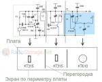
Now let's put this knowledge into practice; from the signal generator we will supply a sinusoid with a frequency of 50 Hz from the signal generator to the TIM5_CH4 input and try to measure its period. In order to speed up the process, I suggest using DMA. Which MK pin corresponds to channel 4 TIM5 can be found in the datasheet on the MK in the section Pinouts and pin description.

For DMA register address required CCR4, here's how to find it. Opening RM0008 and in the table Register boundary addresses find the starting address of TIM5.

offset for register CCR4 can be found in the same document in the section register map.
#include "stm32f10x.h" #define TIM5_CCR4_Address ((u32)0x40000C00+0x40) #define DMA_BUFF_SIZE 2 uint16_t buff;//Buffer uint16_t volatile T; void DMA2_Channel1_IRQHandler (void) ( T = (buff > buff) ? (buff - buff) : (65535+ buff - buff); DMA2->IFCR |= DMA_IFCR_CGIF1; ) void Init_DMA(void) ( RCC->AHBENR |= RCC_AHBENR_DMA2EN ; //Enable clocking of the first DMA module DMA2_Channel1->CPAR = TIM5_CCR4_Address; //Specify the peripheral address - the ADC conversion result register for regular channels DMA2_Channel1->CMAR = (uint32_t)buff; //Set the memory address - the base address of the array in RAM DMA2_Channel1 ->CCR &= ~DMA_CCR1_DIR; //Indicate the direction of data transfer, from the peripheral to the memory DMA2_Channel1->CNDTR = DMA_BUFF_SIZE; //The number of transferred values DMA2_Channel1->CCR &= ~DMA_CCR1_PINC; //The peripheral address is not incremented after each transfer DMA2_Channel1 -> CCR | = DMCR1_MINC; BIT DMA2_ChanNEL1- >CCR |= DMA_CCR1_PL; //Priority - very high DMA2_Channel1->CCR |= DMA_CCR1_CIRC; //Allow DMA work in cyclic mode DMA2_Channel1->CCR |= DMA_CCR1_TCIE;//Enable interrupt at the end of transmission DMA2_Channel1->CCR |= DMA_CCR1_EN; //Enable the operation of the 1st DMA channel) int main(void) ( Init_DMA(); //enable clocking of port A, alternative functions and timer RCC->APB2ENR |= RCC_APB2ENR_IOPAEN | RCC_APB2ENR_AFIOEN; RCC->APB1ENR |= RCC_APB1ENR_TIM5EN; TIM5 ->PSC = 56000-1;//new frequency 1Khz TIM5->CCMR2 |= TIM_CCMR2_CC4S_0;//select TI4 for TIM5_CH4 TIM5->CCMR2 &= ~(TIM_CCMR2_IC4F | TIM_CCMR2_IC4PSC);//do not filter and do not use a divider TIM5- >CCER &= ~TIM_CCER_CC4P;//select capture on the leading edge TIM5->CCER |= TIM_CCER_CC4E;//turn on the capture mode for the 4th channel TIM5->DIER |= TIM_DIER_CC4DE;//allow to generate a request to DMA //TIM5 ->DIER |= TIM_DIER_CC4IE; //enable capture interrupt TIM5->CR1 |= TIM_CR1_CEN; //enable the counter //NVIC->ISER |= NVIC_ISER_SETENA_18; //TIM5 Interrupt NVIC->ISER |= NVIC_ISER_SETENA_24; Interrupt while(1) ( ) )
The STM32 has many very convenient and flexible timers. Even the youngest microcontroller (STM32F030F4P6) has 4 such timers.
8. Set up the project - add the necessary files
To use the timer, we will need to include the peripheral library file stm32f10x_tim.c. Similar, right click In Workspace (window on the left) click on the StdPeriphLib group, Add –> Add files, file LibrariesSTM32F10x_StdPeriph_Driversrcstm32f10x_tim.c.
You also need to enable the use of a header for this file. Open stm32f10x_conf.h (right-click on the name of this file in the code, “Open stm32f10x_conf.h”. Uncomment the line #include “stm32f10x_tim.h”.
9. Add a timer
A delay by an empty cycle is blasphemy, especially on such a powerful crystal as the STM32, with a bunch of timers. Therefore, we will make this delay using a timer.
The STM32 has different timers with different sets of properties. The simplest are Basic timers, the more complex are General purpose timers, and the most complex are Advanced timers. Simple timers are limited to simply counting clock cycles. In more complex timers, PWM appears. The most complex timers, for example, can generate 3-phase PWM with forward and inverse outputs and deadtime. A simple timer, number 6, will suffice for us.
A little theory
All we need from the timer is to count up to a certain value and generate an interrupt (yes, we will also learn how to use interrupts). Timer TIM6 is clocked from system bus, but not directly, but through a prescaler - a simple programmable counter-divider (just think, in the USSR special microcircuit counters were produced, and programmable ones were especially in short supply - and now I’m talking about such a counter just casually). The prescaler can be configured to any value from 1 (i.e. the counter will receive the full bus frequency, 24 MHz) to 65536 (i.e. 366 Hz).
The clock signals, in turn, increment the internal timer counter, starting from zero. As soon as the counter value reaches the ARR value, the counter overflows and the corresponding event occurs. When this event occurs, the timer loads 0 into the counter again and starts counting from zero. At the same time, it can cause an interrupt (if configured).
In fact, the process is a little more complicated: there are two ARR registers - external and internal. During counting, the current value is compared specifically with the internal register, and only when it overflows is the internal one updated from the external one. This way, you can safely change the ARR while the timer is running - at any time.
Code
The code will be very similar to the previous one, because... Initialization of all peripherals occurs in the same way - with the only exception that the TIM6 timer hangs on the APB1 bus. Therefore, enabling the timer: RCC_APB1PeriphClockCmd(RCC_APB1Periph_TIM6, ENABLE);
Now we create a structure of type TIM_TimeBaseInitTypeDef, initialize it (TIM_TimeBaseStructInit), configure it, pass it to the timer initialization function (TIM_TimeBaseInit) and finally turn on the timer (TIM_Cmd).
TIM_TimeBaseInitTypeDef TIM_InitStructure; // Create a structure TIM_TimeBaseStructInit(&TIM_InitStructure); // Initialize the structure TIM_InitStructure.TIM_Prescaler = 24000; // Prescaler TIM_InitStructure.TIM_Period = 1000; // Timer period TIM_TimeBaseInit(TIM6, &TIM_InitStructure); // Function for setting the timer TIM_Cmd(TIM6, ENABLE); // Turn on the timer
What the magic numbers? As we remember, the bus has a clock frequency of 24 MHz (with our project settings). By setting the timer prescaler to 24000, we divide this frequency by 24 thousand and get 1 kHz. This is exactly the frequency that will go to the input of the timer counter.
The value in the counter is 1000. This means that the counter will overflow in 1000 clock cycles, i.e. in exactly 1 second.
After this we actually have a working timer. But that is not all.
10. Let's deal with interruptions
Okay, interruptions. For me once (at the time of PIC) they were a dark forest, and I tried not to use them at all - and I didn’t know how, in fact. However, they contain power that is completely unworthy to ignore. True, interrupts in the STM32 are an even more complex thing, especially the mechanism for displacing them; but more on that later.
As we noted earlier, the timer generates an interrupt when the counter overflows - if interrupt processing for this device is enabled at all, this particular interrupt is enabled and the previous one is reset. Analyzing this phrase, we understand what we need:
- Enable TIM6 timer interrupts in general;
- Enable TIM6 timer interrupt for counter overflow;
- Write an interrupt handler procedure;
- After processing the interrupt, reset it.
Enabling Interrupts
To be honest, there is nothing complicated here at all. First of all, enable TIM6 interrupts: NVIC_EnableIRQ(TIM6_DAC_IRQn); Why this name? Because in the STM32 core, interrupts from TIM6 and from the DAC have the same number. I don’t know why this was done - savings, lack of numbers, or just some kind of legacy thing - in any case, it won’t cause any problems, because this project does not use a DAC. Even if our project used a DAC, we could find out who exactly called it when entering the interrupt. Almost all other timers have a single interrupt.
Configuring the interrupt source event: TIM_ITConfig(TIM6, TIM_DIER_UIE, ENABLE); - enable the TIM6 timer interrupt based on the TIM_DIER_UIE event, i.e. ARR value update event. As we remember from the picture, this happens simultaneously with the counter overflow - so this is exactly the event that we need.
At the moment, the code for timer cases is as follows:
RCC_APB1PeriphClockCmd(RCC_APB1Periph_TIM6, ENABLE); TIM_TimeBaseInitTypeDef TIM_InitStructure; TIM_TimeBaseStructInit(&TIM_InitStructure); TIM_InitStructure.TIM_Prescaler = 24000; TIM_InitStructure.TIM_Period = 1000; TIM_TimeBaseInit(TIM6, &TIM_InitStructure); TIM_Cmd(TIM6, ENABLE); NVIC_EnableIRQ(TIM6_DAC_IRQn); TIM_ITConfig(TIM6, TIM_DIER_UIE, ENABLE);
Interrupt handling
Now you can’t run the project - the very first interrupt from the timer will not find its handler, and the controller will hang (more precisely, it will end up in the HARD_FAULT handler, which is essentially the same thing). We need to write it.
A little theory
It must have a very specific name, void TIM6_DAC_IRQHandler(void). This name, the so-called interrupt vector, is described in the startup file (in our project it is startup_stm32f10x_md_vl.s - you can see for yourself, line 126). In fact, the vector is the address of the interrupt handler, and when an interrupt occurs, the ARM core climbs into the initial area (to which the startup file is translated - i.e. its location is set completely rigidly, at the very beginning of flash memory), looks for the vector there and moves to the right place in the code.
Event check
The first thing we must do when entering such a handler is to check which event caused the interrupt. Now we have only one event, but in a real project there may well be several events on one timer. Therefore, we check the event and execute the corresponding code.
In our program, this check will look like this: if (TIM_GetITStatus(TIM6, TIM_IT_Update) != RESET) - everything is clear, the TIM_GetITStatus function checks for the presence of the specified event on the timer and returns 0 or 1.
Clearing the UIF flag
The second step is to clear the interrupt flag. Return to the picture: the very last UIF graph is the interrupt flag. If it is not cleared, the next interrupt will not be called, and the controller will again fall into HARD_FAULT (what is that!).
Executing Actions in an Interrupt
We will simply switch the state of the LED, as in the first program. The difference is that now our program makes it more difficult! In fact, it is much more correct to write this way.
If(state) GPIO_WriteBit(GPIOC, GPIO_Pin_8, Bit_SET); else GPIO_WriteBit(GPIOC, GPIO_Pin_8, Bit_RESET); state = 1 - state;
We use the global variable int state=0;
11. All project code with a timer
#include "stm32f10x_conf.h" int state=0; void TIM6_DAC_IRQHandler(void) ( if (TIM_GetITStatus(TIM6, TIM_IT_Update) != RESET) ( TIM_ClearITPendingBit(TIM6, TIM_IT_Update); if(state) GPIO_WriteBit(GPIOC, GPIO_Pin_8, Bit_SET); else GPIO_WriteBit(GPIOC, GPIO_ Pin_8, Bit_RESET); = 1 - state; ) ) void main() ( RCC_APB2PeriphClockCmd(RCC_APB2Periph_GPIOC, ENABLE); GPIO_InitTypeDef GPIO_InitStructure; GPIO_StructInit(&GPIO_InitStructure); GPIO_InitStructure.GPIO_Speed = GPIO_Speed_2MHz; GPIO_InitS tructure.GPIO_Mode = GPIO_Mode_Out_PP; GPIO_InitStructure.GPIO_Pin = GPIO_Pin_8; GPIO_Init(GPIOC, &GPIO_InitStructure ); GPIO_WriteBit(GPIOC, GPIO_Pin_8, Bit_SET); RCC_APB1Periph_TIM6, ENABLE); r = 24000; TIM_InitStructure.TIM_Period = 1000; TIM_TimeBaseInit(TIM6, &TIM_InitStructure); ); NVIC_EnableIRQ(TIM6_DAC_IRQn); TIM_ITConfig(TIM6, TIM_DIER_UIE, ENABLE);Archive with the timer project.
Well, by the way, the timer can switch the leg itself, without interruptions or manual processing. This will be our third project.
Whole cycle:
1. I/O ports
2. Timer and interrupts
3. Timer outputs
4. External interrupts and NVIC
5. Install FreeRTOS
Post Views: 235