For the given function, construct a truth table
Electrical diagram, designed to perform some logical operation with input data, is called a logical element. The input data is represented here in the form of voltages of various levels, and the result of the logical operation at the output is also obtained in the form of a voltage of a certain level.
In this case, the operands are supplied - signals in the form of a high or low level voltage are received at the input of the logic element, which essentially serve as input data. Thus, a high level voltage - a logical 1 - indicates a true value of the operand, and a low level voltage 0 - a false value. 1 - TRUE, 0 - FALSE.
Logic element- an element that implements certain logical relationships between input and output signals. Logic elements are usually used to construct logical circuits of computers and discrete automatic monitoring and control circuits. All types of logical elements, regardless of their physical nature, are characterized by discrete values of input and output signals.
Logic elements have one or more inputs and one or two (usually inverse to each other) outputs. The values of “zeros” and “ones” of the output signals of logical elements are determined by the logical function that the element performs, and the values of “zeros” and “ones” of the input signals, which play the role of independent variables. There are elementary logical functions from which any complex logical function can be composed.
Depending on the design of the element circuit, on its electrical parameters, logical levels (high and low levels voltages) input and output have the same values for high and low (true and false) states.
Traditionally, logic elements are produced in the form of special radio components - integrated circuits. Logical operations such as conjunction, disjunction, negation and modulo addition (AND, OR, NOT, XOR) are the basic operations performed on the main types of logical gates. Next, let's look at each of these types of logic elements more closely.
Logic element "AND" - conjunction, logical multiplication, AND

“AND” is a logical element that performs a conjunction or logical multiplication operation on the input data. This element can have from 2 to 8 (the most common in production are “AND” elements with 2, 3, 4 and 8 inputs) inputs and one output.
Symbols of logical elements “AND” with different numbers of inputs are shown in the figure. In the text, a logical element “AND” with one or another number of inputs is designated as “2I”, “4I”, etc. - an “AND” element with two inputs, with four inputs, etc.
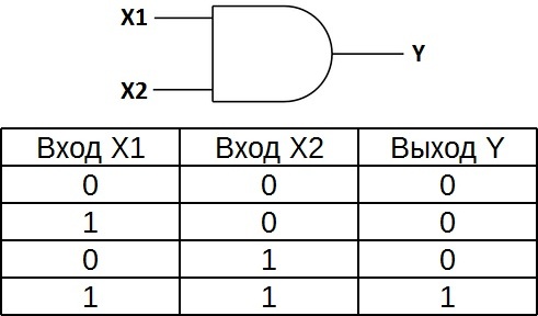
The truth table for element 2I shows that the output of the element will be a logical one only if logical ones are simultaneously at the first input AND at the second input. In the remaining three possible cases, the output will be zero.
In Western diagrams, the “AND” element icon has a straight line at the input and a rounded line at the output. On domestic diagrams - a rectangle with the symbol “&”.
Logical element "OR" - disjunction, logical addition, OR
“OR” is a logical element that performs a disjunction or logical addition operation on the input data. It, like the “I” element, is available with two, three, four, etc. inputs and one output. Symbols of logical elements "OR" with varying amounts inputs are shown in the figure. These elements are designated as follows: 2OR, 3OR, 4OR, etc.

The truth table for the “2OR” element shows that for a logical one to appear at the output, it is sufficient that the logical one be at the first input OR at the second input. If there are logical ones at two inputs at once, the output will also be one.
In Western diagrams, the “OR” element icon has a rounded shape at the input and a rounded point with a sharp point at the output. On domestic diagrams there is a rectangle with the symbol “1”.
Logic element "NOT" - negation, inverter, NOT

“NOT” is a logical element that performs a logical negation operation on the input data. This element, which has one output and only one input, is also called an inverter, since it actually inverts (reverses) the input signal. The figure shows the symbol for the logical element “NOT”.
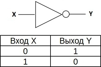
The truth table for an inverter shows that a high input potential produces a low output potential and vice versa.
In Western diagrams, the “NOT” element icon has the shape of a triangle with a circle at the output. On domestic diagrams there is a rectangle with the symbol “1”, with a circle at the output.
Logic element "NAND" - conjunction (logical multiplication) with negation, NAND

“AND-NOT” is a logical element that performs a logical addition operation on the input data, and then a logical negation operation, the result is sent to the output. In other words, it is basically an “AND” element, complemented by a “NOT” element. The figure shows the symbol for the logical element “2AND-NOT”.

The truth table for the NAND gate is the opposite of the truth table for the AND gate. Instead of three zeros and a one, there are three ones and a zero. The NAND element is also called the Schaeffer element in honor of the mathematician Henry Maurice Schaeffer, who first noted its significance in 1913. Denoted as “I”, only with a circle at the output.
Logical element "OR-NOT" - disjunction (logical addition) with negation, NOR
“OR-NOT” is a logical element that performs a logical addition operation on the input data, and then a logical negation operation, the result is sent to the output. In other words, this is an “OR” element supplemented by a “NOT” element - an inverter. The figure shows the symbol for the logical element “2OR-NOT”.

The truth table for an OR gate is the opposite of the truth table for an OR gate. A high potential at the output is obtained only in one case - low potentials are simultaneously applied to both inputs. It is designated as “OR”, only with a circle at the output indicating inversion.
Logic gate "exclusive OR" - addition modulo 2, XOR

“exclusive OR” is a logical element that performs a logical addition operation modulo 2 on the input data, has two inputs and one output. Often these elements are used in control circuits. The figure shows the symbol for this element.
The image in Western circuits is like “OR” with an additional curved strip on the input side, in domestic ones it is like “OR”, only instead of “1” it will be written “=1”.
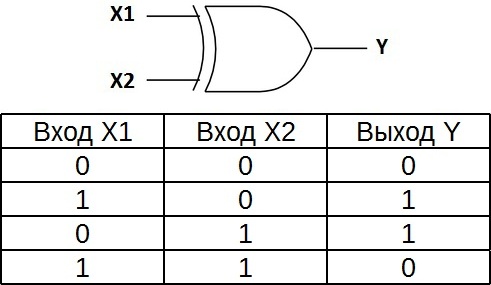
This logical element is also called “unequivalence”. High level voltage will be at the output only when the signals at the input are not equal (one is one, the other is zero, or one is zero, and the other is one); even if there are two units at the input at the same time, the output will be zero - this is the difference from “ OR". These logic elements are widely used in adders.
The problem of determining the truth of an expression faces many sciences. Any evidentiary discipline must be based on some criteria for the truth of evidence. The science that studies these criteria is called the algebra of logic. The main postulate of the algebra of logic is that any most ornate statement can be represented as an algebraic expression of simpler statements, the truth or falsity of which is easy to determine.
For any “algebraic” operation on a statement, a rule is specified for determining the truth or falsity of the modified statement, based on the truth or falsity of the original statement. These rules are written through expression truth tables. Before compiling truth tables, you need to become more familiar with the algebra of logic.
Algebraic transformations of logical expressions
Any logical expression, as well as its variables (statements), take two values: lie or truth. False is denoted by zero, and truth is denoted by one. Having understood the domain of definition and the region acceptable values, we can consider the operations of the algebra of logic.
Negation
Negation and inversion- the simplest logical transformation. It corresponds to the particle "not." This transformation simply reverses the statement. Accordingly, the meaning of the statement also changes to the opposite. If statement A is true, then "not A" is false. For example, the statement “a right angle is an angle equal to ninety degrees” is true. Then his denial "a right angle is not equal to ninety degrees" is a lie.
Truth table for negation will be like this:
Disjunction
This operation may be ordinary or strict, their results will vary.
The usual disjunction or logical addition corresponds to the conjunction "or". It will be true if at least one of the statements included in it is true. For example, the expression “The earth is round or stands on three pillars” will be true, since the first statement is true, although the second is false. In the table it will look like this:
Strict disjunction or modulo addition is also called "exclusive or". This operation can take the form of a grammatical construction “one of two: either... or...”. Here, the value of a logical expression will be false if all statements included in it have the same truth. That is, both statements are either together true or together false.
Table of exclusive or
Implication and equivalence
The implication is consequence and can be grammatically expressed as “from A follows B.” Here statement A will be called a premise, and B will be called a consequence. An implication can be false only in one case: if the premise is true and the consequence is false. That is, a lie cannot follow from the truth. In all other cases the implication is true. Options when both statements have the same truth do not raise questions. But why is a true consequence from a false premise true? The point is that anything can follow from a false premise. This is what distinguishes implication from equivalence.
In mathematics (and other demonstrative disciplines), implication is used to specify a necessary condition. For example, statement A is “point O is the extremum of a continuous function,” statement B is “the derivative of a continuous function at point O becomes zero.” If O is indeed the extremum point of a continuous function, then the derivative at this point will indeed be equal to zero. If O is not an extremum point, then the derivative at this point may or may not be zero. That is, B is necessary for A, but not sufficient.

Truth table for implication looks like this:
The logical operation of equivalence is essentially mutual implication. “A is equivalent to B” means that “from A follows B” and “from B follows A” at the same time. Equivalence is true when both statements are either simultaneously true or simultaneously false.
In mathematics, equivalence is used to determine a necessary and sufficient condition. For example, statement A - “Point O is the extremum point of a continuous function”, statement B - “At point O, the derivative of the function becomes zero and changes sign.” These two statements are equivalent. B contains a necessary and sufficient condition for A. Note that in in this example statements B is actually a conjunction of two others: “the derivative at point O becomes zero” and “the derivative at point O changes sign.”

Other logic functions
Above we discussed the basic logical operations that are often used. There are other functions that are used:
- The Schaeffer stroke or incompatibility is the negation of the conjunction of A and B
- Peirce's arrow represents the failure of the negation of the disjunction.
Construction of truth tables
To build a truth table for any logical expression, you must act in accordance with the algorithm:
- Break the expression down into simple statements and label each as a variable.
- Define logical transformations.
- Identify the order of these transformations.
- Count the rows in the future table. Their number is equal to two to the power of N, where N is the number of variables, plus one line for the table header.
- Determine the number of columns. It is equal to the sum of the number of variables and the number of actions. You can represent the result of each action as a new variable, if that makes sense.
- The header is filled in sequentially, first all the variables, then the results of the actions in the order in which they were performed.
- You need to start filling out the table with the first variable. For her, the number of lines is divided in half. One half is filled with zeros, the second with ones.
- For each subsequent variable, zeros and ones alternate twice as often.
- This way all columns with variables are filled in and for the last one variable value changes on every line.
- Then the results of all actions are sequentially filled in.
As a result, the last column will display the value of the entire expression depending on the value of the variables.

Special mention should be made about order of logical actions. How to determine it? Here, as in algebra, there are rules that determine the sequence of actions. They are performed in the following order:
- expressions in brackets;
- negation or inversion;
- conjunction;
- strict and ordinary disjunction;
- implication;
- equivalence.

Examples
To consolidate the material, you can try to create a truth table for the previously mentioned logical expressions. Let's look at three examples:
- Schaeffer's stroke.
- Pierce's arrow.
- Definition of equivalence.
Schaeffer's stroke
A Schaeffer stroke is a Boolean expression that can be written as "not (A and B)". There are two variables and two actions. The conjunction is in parentheses, which means it is executed first. The table will have a header and four rows with variable values, as well as four columns. Let's fill out the table:
| A | B | A and B | not (A and B) |
| L | L | L | AND |
| L | AND | L | AND |
| AND | L | L | AND |
| AND | AND | AND | L |
The negation of a conjunction looks like a disjunction of negations. This can be verified by constructing a truth table for the expression “not A or not B.” Do this yourself and note that there will already be three operations here.
Pierce's arrow
Considering Peirce's Arrow, which represents the negation of the disjunction "not (A or B)", let's compare it with the conjunction of negations "not A and not B". Let's fill in two tables:
| A | B | not A | not B | not A and not B |
| L | L | AND | AND | AND |
| L | AND | AND | L | L |
| AND | L | L | AND | AND |
| AND | AND | L | L | L |
The meanings of the expressions coincided. After studying these two examples, we can come to a conclusion about how to open parentheses after negation: negation is applied to all variables in the parentheses, conjunction changes to disjunction, and disjunction changes to conjunction.
Definition of equivalence
We can say about statements A and B that they are equivalent if and only if A follows from B and B follows from A. Let's write this as a logical expression and build a truth table for it. "(A is equivalent to B) is equivalent to (from A follows B) and (from B follows A)."
There are two variables and five actions. We build the table:
All values in the last column are true. This means that the above definition of equivalence is true for any values of A and B. This means that it is always true. That's right using truth table you can check the correctness of any definitions and logical constructions.
Lesson duration: 45 min
Lesson type: combined:
- knowledge test - oral work;
- new material - lecture;
- consolidation – practical exercises;
- knowledge testing - tasks for independent work.
Lesson objectives:
- give the concept of a truth table;
- consolidation of the material from the previous lesson “Algebra of Propositions”;
- usage information technology;
- instilling the skill of independently searching for new material;
- development of curiosity and initiative;
- education of information culture.
Lesson plan:
- Organizational moment (2 min).
- Repetition of material from the previous lesson (oral questioning) (4 min).
- Explanation of new material (12 min).
- Consolidation
- case study (5 min);
- practical exercises (10 min);
- assignments for independent work(10 min).
Equipment and software material:
- white board;
- multimedia projector;
- computers;
- presentation editor MS PowerPoint 2003;
- handout reference material “Truth Tables”;
- Demonstration of the “Truth Table” presentation.
Lesson progress
I. Organizational moment
We continue to study the topic “Fundamentals of Logic”. In previous lessons, we saw that logic is quite closely connected with our everyday life, and we also saw that almost any statement can be written as a formula.
II. Repetition of material from the previous lesson
Let's remember the basic definitions and concepts:
| Question | Answer |
| 1. Which sentence is a statement? | A declarative sentence that states or denies something |
| 2. What types of statements are divided into according to their structure? | Simple and complex |
| 3. The truth of which statements is contractual? | Simple |
| 4. The truth of which statements is being calculated? | Complex |
| 5. How are simple statements denoted in propositional algebra? | Boolean variables |
| 6. How is the truth of such statements indicated? | 1 and 0 |
| 7. What connects variables in propositional algebra formulas? | Logical operations |
| 8. List them. | Inversion (negation) Conjunction (multiplication) Disjunction (addition) Implication (following) Equivalence (equivalence) |
| 9. Determine whether the formula corresponds to a complex statement. Name simple statements. Determine the cause of the nonconformity. (Task on screen) | No, the sign is placed incorrectly |
| 10. Determine whether the formula corresponds to a complex statement. Name simple statements. Determine the cause of the nonconformity. (Task on screen) | Yes |
III. Explanation of new material
The last two examples refer to complex statements. How to determine the truth of complex statements?
We said that it is calculated. For this purpose, in logic there are tables for calculating the truth of compound (complex) statements. These are called truth tables.
So, the topic of the lesson is TRUTH TABLES.
3.1) Definition. A truth table is a table showing the truth of a complex statement for all possible values of the input variables (Figure 1).
3.2) Let us examine in more detail each logical operation in accordance with its definition:
1. Inversion (negation) is a logical operation that associates each simple statement with a compound statement, which means that the original statement is negated.
This operation applies to only one variable, so only two lines, because one variable can have one of two values: 0 or 1.
2. Conjunction (multiplication) is a logical operation that associates each two simple statements with a compound statement that is true if and only if both original statements are true.
It is easy to see that this table is indeed similar to a multiplication table.
3. Disjunction (addition) is a logical operation that associates each two simple statements with a compound statement that is false if and only if both initial statements are false.
You can make sure that the table is similar to the addition table except for the last step. In the binary number system 1 + 1 = 10, in the decimal number system – 1 + 1 = 2. In logic, the value of variable 2 is impossible, let’s consider 10 from the point of view of logic: 1 – true, 0 – false, i.e. 10 is true and false at the same time, which cannot be, so the last action is strictly based on the definition.
4. Implication (following) is a logical operation that associates each two simple statements with a compound statement that is false if and only if the condition is true and the consequence is false.
5. Equivalence (equivalence) is a logical operation that associates each two simple statements with a compound statement that is true if and only if both initial statements are simultaneously true or false.
The last two operations were discussed by us in the previous lesson.
3.3) Let's look at it truth table algorithm for a complex statement:
3.4) Consider an example of compiling a truth table for a complex statement:
Example. Construct a truth table for the formula: A U B -> ¬A U C.
Solution (Figure 2)

The example shows that the truth table is not the entire decision, but only the last action (the column highlighted in red).
IV. Consolidation.
To consolidate the material, you are asked to solve the examples under the letters a, b, c, and additionally d–g on your own (Figure 3).

V. Homework, summarizing the material.
Homework is also given to you on the monitor screen (Figure 4)

Summary of material: Today in the lesson we learned how to determine the truth of compound statements, but more from a mathematical point of view, since you were given not the statements themselves, but formulas that display them. In the following lessons we will consolidate these skills and try to apply them to solving logical problems.
Logic function is a function in which variables take only two values: logical one or logical zero. The truth or falsity of complex propositions is a function of the truth or falsity of simple ones. This function is called the Boolean judgment function f (a, b).
Any logical function can be specified using a truth table, on the left side of which a set of arguments is written, and on the right side - the corresponding values logical function.
When constructing a truth table, it is necessary to take into account the order of execution logical operations. Operations in a logical expression are performed from left to right, taking into account parentheses, in the following order:
- 1. inversion;
- 2. conjunction;
- 3. disjunction;
- 4. implication and equivalence.
To change the specified order of logical operations, parentheses are used.
The following is proposed truth table construction algorithm.
- 1. Define number of sets of input variables- all possible combinations of values of variables included in expressions, according to the formula: Q=2 n, where n is the number of input variables. It determines the number of rows in the table.
- 2. Enter all sets of input variables into the table.
- 3. Determine the number of logical operations and the sequence of their execution.
- 4. Fill in the columns with the results of performing logical operations in the indicated sequence.
In order not to repeat or miss any possible combination of values of input variables, you should use one of the methods suggested below for filling out the table.
Method 1. Each set of values of the original variables is a number code in binary system notation, and the number of digits of the number is equal to the number of input variables. The first set is the number 0. By adding 1 to the current number each time, we get the next set. Last set - maximum value binary number for a given code length.
For example, for a function of three variables, the sequence of sets consists of numbers:
Method 2. For a function of three variables, the data sequence can be obtained as follows:
- a) divide the column of values of the first variable in half and fill the upper half with zeros, the lower half with ones;
- b) in the next column for the second variable, divide the half in half again and fill it with groups of zeros and ones; fill the other half in the same way;
- c) do this until the groups of zeros and ones consist of one character.
Method 3. Use the known truth table for the two arguments. When adding a third argument, first write the first 4 rows of the table, combining them with the value of the third argument equal to 0, and then write the same 4 rows again, but now with the value of the third argument equal to 1. As a result, the table for three arguments will be 8 lines:
For example, let's build a truth table for a logical function:
The number of input variables in a given expression is three (A,B,C). This means that the number of input sets Q=2 3 =8 .
The columns of the truth table correspond to the values of the original expressions A,B,C, intermediate results and ( B V C), as well as the desired final value of a complex arithmetic expression:
- 0 0 0 1 0 0
- 0 0 1 1 1 1
- 0 1 0 1 1 1
- 0 1 1 1 1 1
- 1 0 0 0 0 0
- 1 0 1 0 1 0
- 1 1 0 0 1 0
- 1 1 1 0 1 0
- 7.4. Logical functions and their transformations. Laws of logic
For the operations of conjunction, disjunction and inversion, the laws of Boolean algebra are defined, allowing identical (equivalent) transformations of logical expressions.
Laws of logic
- 1. ¬¬A
- 2. A&B
- 3.AVB
- 4. A&(B&C)
- 5.AV(BVC)
- 6. A&(BVC)
- 7.AV(B&C)
- 8. A&A
- 9.AVA
- 10. AV¬A
- 11. A&¬A
- 12. A&I
- 13. AVI
- 14. A&L
- 15. AVL
- 16.¬(A&B)
- 17.¬(AVB)
- 18. A => B
Based on the laws, it is possible to simplify complex logical expressions. This process of replacing a complex logical function with a simpler but equivalent one is called function minimization.
Example 1. Simplify the expressions so that the resulting formulas do not contain the negation of complex statements.
Solution

Example 2. Minimize function
To simplify the expression, the absorption and adhesion formulas were used.
Example 3. Find the negation of the following statement: “If the lesson is interesting, then none of the students (Misha, Vika, Sveta) will look out the window.”
Solution
Let us denote the statements:
Y- “The lesson is interesting”;
M- “Misha looks out the window”;
B- “Vika looks out the window”;
C- “Sveta is looking out the window.”

When simplifying the expression, the formula for replacing operations and De Morgan's law were used.
Example 4. Determine the participant in the crime based on two premises: logical computer table
- 1) “If Ivanov did not participate or Petrov participated, then Sidorov participated”;
- 2) “If Ivanov did not participate, then Sidorov did not participate.”
Solution
Let's make up the expressions:
I- “Ivanov participated in the crime”;
P- “Petrov participated in the crime”;
S- "Sidorov participated in the crime."
Let's write the premises in the form of formulas:

Let's check the result using the truth table:

Answer: Ivanov participated in the crime.
Constructing a logical function from its truth table
We learned how to create a truth table for a logical function. Let's try to solve the inverse problem.
Consider the rows where the truth value of the function Z is true (Z=1). The function for this truth table can be written as follows: Z(X,Y) = (¬ X& ¬Y)V(X& ¬Y).
Each line where the function is true (equal to 1) corresponds to a bracket representing a conjunction of arguments, and if the value of the argument is O, then we take it with negation. All brackets are connected to each other by the disjunction operation. The resulting formula can be simplified by applying the laws of logic:
Z(X,Y)<=>((¬X& ¬Y) VX)&((¬X&Y)V ¬Y)<=>(XV(¬X& ¬Y)) &(¬YV(¬X&¬Y))<=>((XV¬X)&(XV ¬Y))&((Y¬V ¬X)&(¬YV ¬Y))<=>(1&(XV ¬Y))&((¬YV ¬X)& ¬Y)<=>(XV ¬Y)&((¬YV ¬X)& ¬Y).
Check the resulting formula: create a truth table for the function Z(X,Y).
Write down the rules for constructing a logical function using its truth table:
- 1. Select those rows in the truth table in which the function value is equal to 1.
- 2. Write down the required formula in the form of a disjunction of several logical elements. The number of these elements is equal to the number of selected lines.
- 3. Write each logical element in this disjunction as a conjunction of function arguments.
- 4. If the value of any function argument is in corresponding line table is 0, then we take this argument with negation.
Construction of truth tables for complex statements.
Priority of logical operations
1) inversion 2) conjunction 3) disjunction 4) implication and equivalence
How to create a truth table?
According to the definition, the truth table of a logical formula expresses the correspondence between all possible sets of variable values and the values of the formula.
For a formula that contains two variables, there are only four such sets of variable values:
(0, 0), (0, 1), (1, 0), (1, 1).
If a formula contains three variables, then there are eight possible sets of variable values (0, 0, 0), (0, 0, 1), (0, 1, 0), (0, 1, 1), (1, 0, 0 ), (1, 0, 1), (1, 1, 0), (1, 1, 1).
The number of sets for a formula with four variables is sixteen, etc.
A convenient form of recording when finding the values of a formula is a table containing, in addition to the values of variables and formula values, also the values of intermediate formulas.
Examples.
1. Let's create a truth table for the formula 96%" style="width:96.0%">
From the table it is clear that for all sets of values of the variables x and y, the formula takes the value 1, that is, is identical to true.
2. Truth table for the 96% formula" style="width:96.0%">
From the table it is clear that for all sets of values of the variables x and y, the formula takes value 0, that is, is identically false .
3. Truth table for the formula 96%" style="width:96.0%">
From the table it is clear that formula 0 " style="border-collapse:collapse;border:none">
Conclusion: we got all ones in the last column. This means that the meaning of the complex statement is true for any meaning of the simple statements K and S. Consequently, the teacher reasoned logically correctly.